
Integrated grinding pad and its mfg. method

The integrated structure of the elastic support layer and the polishing layer composed of chemically compatible materials solves the problems of low efficiency and complex manufacturing of existing polishing pads in the polishing process, achieves efficient planarization and real-time detection, simplifies the process and reduces the cost. cost.

Inactive Publication Date: 2004-05-12
KPX CHEM
View PDF3 Cites 7 Cited by
  • Summary
  • Abstract
  • Description
  • Claims
  • Application Information

AI Technical Summary

Problems solved by technology

However, the polishing pad of U.S. Patent No. 5,605,760 requires a process of punching the pad and then installing the transparent window in the pad in order to form a transparent window through which light beams can pass, making the manufacturing process complicated.
And, in the polishing process, the movement and delivery of the abrasive slurry are hindered by the gaps in the connection between the transparent window and the pad, and at the same time, the slurry deposited in the gaps becomes agglomerated, which may cause scratches on the surface of the wafer. mark
In addition, since the substance of the transparent window and the remaining part of the pad are different, scratches may be generated centering on the transparent window during the polishing process.
In U.S. Patent No. 6,171,181, there is disclosed a polishing pad that forms a transparent part in the pad by cooling a certain part in the mold more rapidly than other parts, but if such a polishing pad is to be manufactured, it can be adjusted as needed. Special molds for different temperatures, so the cost will increase
Also, for the pads disclosed in U.S. Patent No. 5,605,760 and U.S. Patent No. 6,171,181, since the hysteresis loss cannot be minimized, an elastic support layer is also required, for which reason it is also necessary to form a transparent window or The transparent part complicates the manufacturing process of the polishing pad

Method used


Image

  • Integrated grinding pad and its mfg. method
  • Integrated grinding pad and its mfg. method
  • Integrated grinding pad and its mfg. method

Examples


Embodiment 2

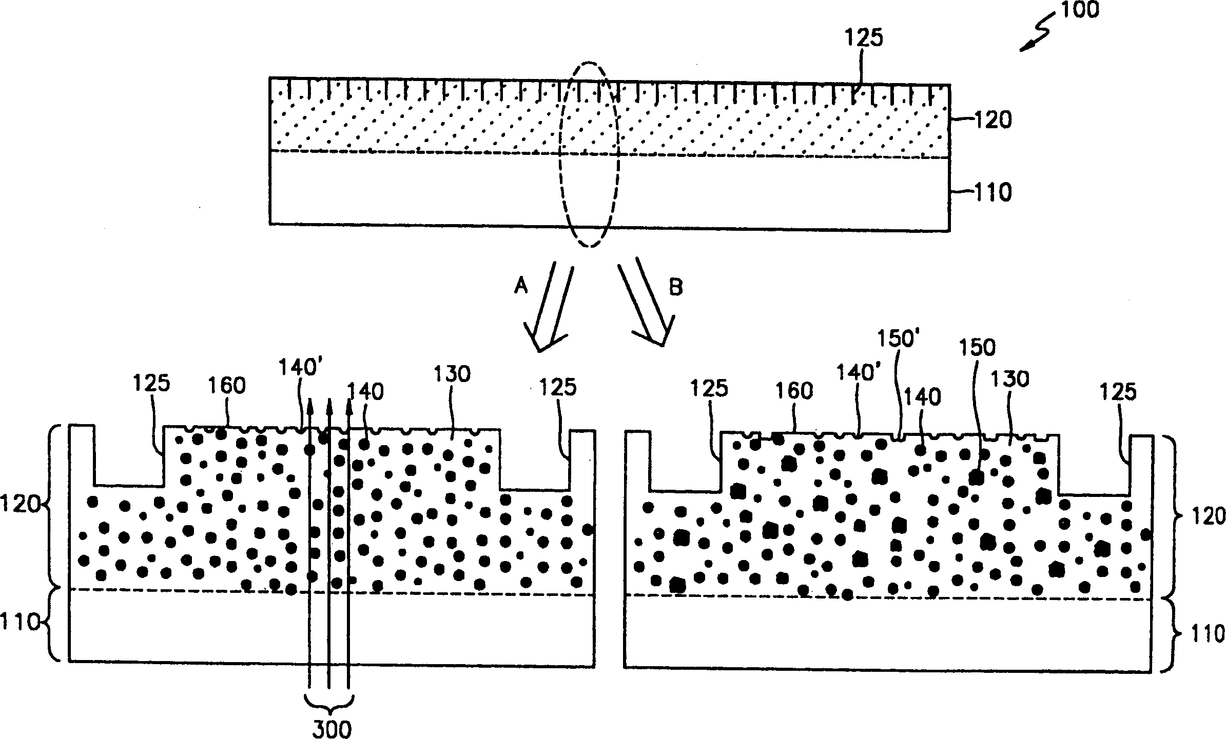
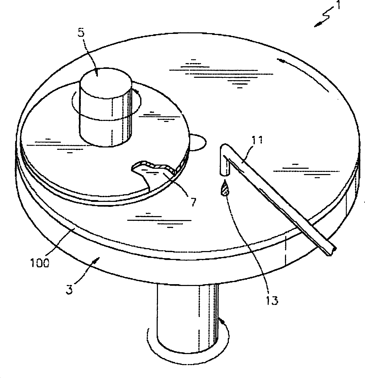
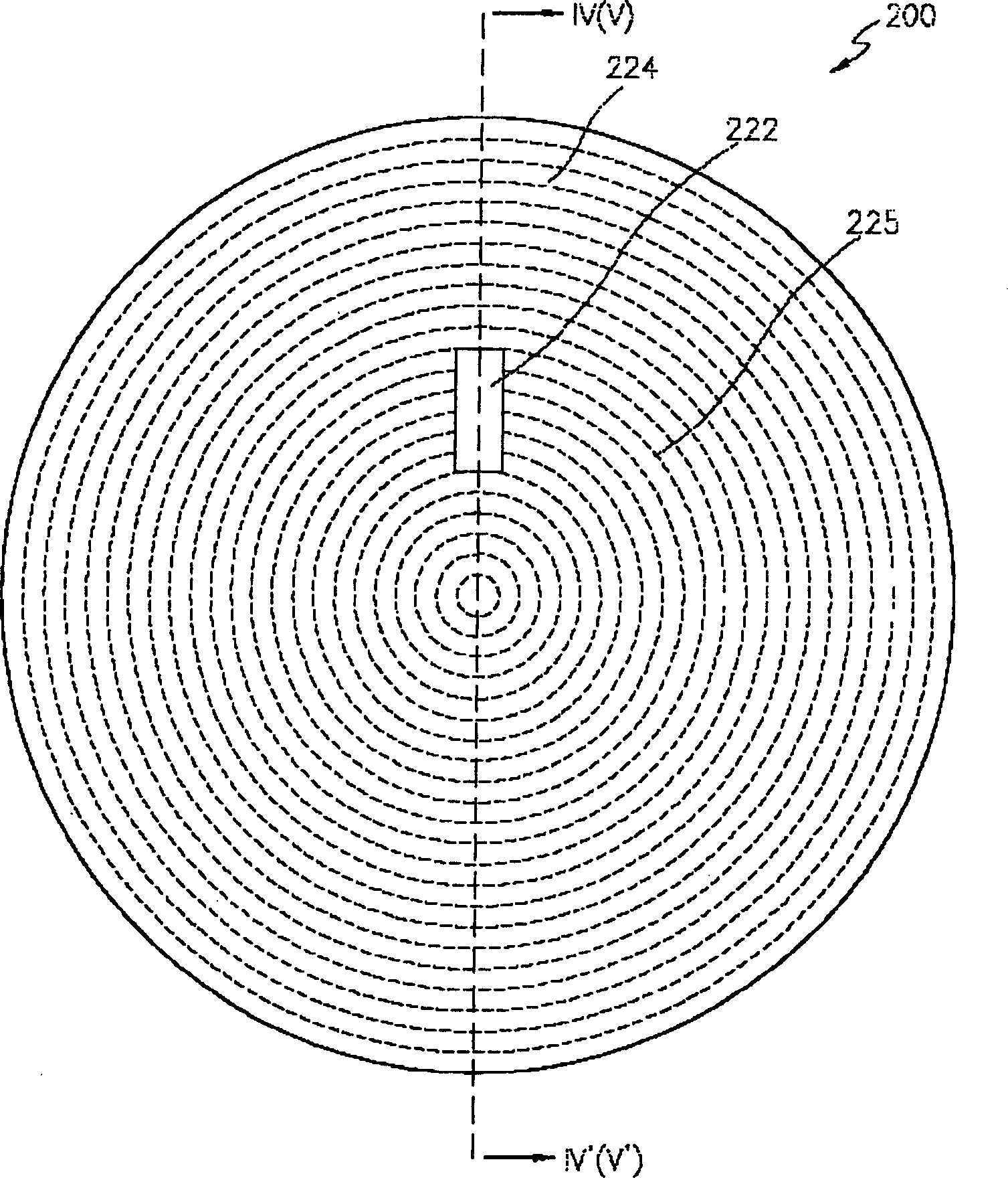
[0040] The polishing pad 200 of the second embodiment further has a transparent region 222 transparent to the light source 300 for optically detecting the surface state of the object to be polished, that is, the flatness of the wafer surface. On the surface of the polishing pad 200 is formed a texture or pattern 225 having a flow channel that facilitates the movement and delivery of the polishing slurry. Such as Figure 4 As shown, in the polishing pad 200 of Example 2, the elastic supporting layer 210, the transparent region 222 constituting the polishing layer 220, and the other region 224 are integrated. The so-called integral type, as described in Embodiment 1, means that the elastic support layer 210, the transparent region 222 of the grinding layer 220 and the other region 224 are made of materials that are chemically compatible with each other, so that the elastic support layer 210 and the There is no structural boundary between the regions 222, 224 of the abrasive lay...

Embodiment 1

[0062] 100 g of a polyether-based isocyanate prepolymer (NCO content: 16%) and 100 g of polypropylene glycol were mixed at normal temperature, and the reaction was started. While maintaining a low viscosity, the reaction liquid was casted with a thickness of 1.5 mm, gelled for 30 minutes, and then cured in an oven at 100° C. for 20 hours. Then, the obtained cured product was cut into a certain size to manufacture a support layer. A sheet having a thickness of 1 mm was produced by the same method as that of the support layer, and cut into a size of 20 mm×50 mm to form a transparent window.

[0063] A prefabricated support layer was installed in a mold of a certain size, a transparent window was placed on the surface of the support layer, and the temperature of the mold was adjusted to 50° C. to produce a polishing layer.

[0064] Mixed polyether-based isocyanate prepolymer (NCO content 11%) 100g, mineral oil (hereinafter referred to as KF-70) (manufactured by Seojin Chemical C...

Embodiment 3

[0068] A polishing layer was produced in the same manner as in Example 1. After the obtained polishing layer was punched out to a size of 20mm×50mm to form an empty space, it was installed in a mold of a certain size, and the temperature of the mold was adjusted to 50°C.

[0069] Urethane produced according to the method of forming a transparent window in Example 1 was injected into the empty space of the abrasive layer in the above mold. Then, the urethane reactant for forming the support layer of Example 1 was injected over the polishing layer to perform casting processing. After gelling for 30 minutes, it was cured in an oven at 100° C. for 20 hours, and then removed from the mold and processed to complete the polishing pad.

[0070] According to the polishing pad of the present invention, since the elastic supporting layer and the polishing layer are integrated, the flattening efficiency of the object to be polished is improved, and since the whole is formed as a thin pla...


PUM

PropertyMeasurementUnit
diameteraaaaaaaaaa
hardnessaaaaaaaaaa
percent by massaaaaaaaaaa

Abstract

An integral polishing pad includes an elastic support layer and a polishing layer, which is formed on the elastic support layer and has a higher hardness than the elastic support layer. The elastic support layer and the polishing layer are made from materials chemically compatible with each other so that a structural border between the elastic support layer and the polishing layer does not exist. In addition, the integral polishing pad also includes a transparent region, which is transparent to a light source used to detect the surface state of an object being polished and integrated with the other elements of the integral polishing pad. The integral polishing pad has high planarization efficiency and uniform properties, and thus can be reliably used for polishing. In addition, the integral polishing pad prevents a congestion of a polishing slurry and facilitates delivery of the polishing slurry. The integral polishing pad does not need an adhesive for connecting elements or a process for bonding the elements, thereby simplifying manufacturing processes.

Description

technical field [0001] The present invention relates to a polishing pad and a manufacturing method thereof, in particular to a polishing pad in which an elastic support layer and a polishing layer are integrated and a manufacturing method thereof. Background technique [0002] With the high integration and miniaturization of semiconductors and the multi-layered wiring structure, in the chemical mechanical polishing process introduced for the overall planarization of semiconductor elements, the polishing speed and planarization speed are more important, and these depend on Engineering conditions of grinding equipment, types of grinding liquid, types of pads, etc. In particular, the polishing pad, which is in direct contact with the wafer in the polishing process and is a consumable part, functions as an important factor determining the performance of the polishing process. [0003] U.S. Patent No. 5,257,478 discloses a polishing pad that elastically compresses and expands th...

Claims


Application Information

Patent Timeline
Patent Type & Authority Applications(China)
IPC IPC(8): B24B1/00B24B37/07B24B37/20B24B37/22B24B37/24B24D3/00B24D3/32B24D11/00H01L21/304
CPCB24B37/205B24D3/32Y10T428/24372Y10T428/24405Y10T428/24612Y10T428/24983Y10T428/2984Y10T428/249978Y10T428/24998Y10T428/249988B24D11/00
Inventor 许铉李尚目宋基千金承根孙镀权
Owner KPX CHEM
Learn More