

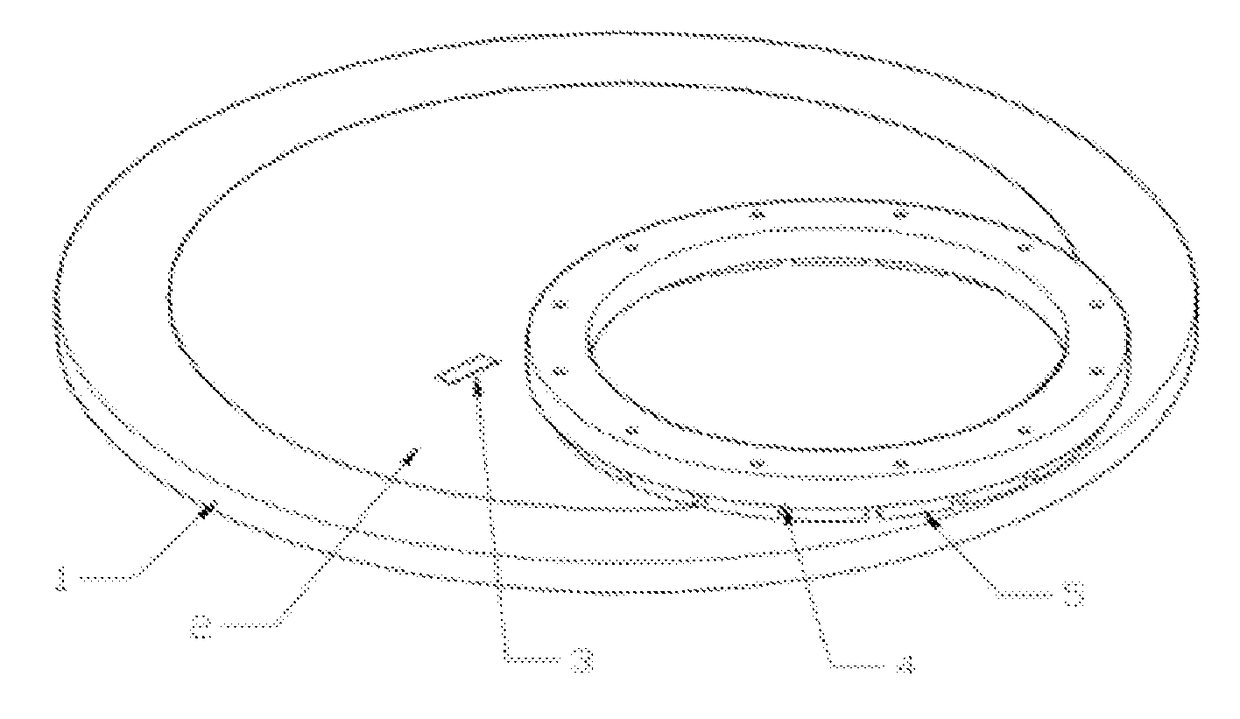
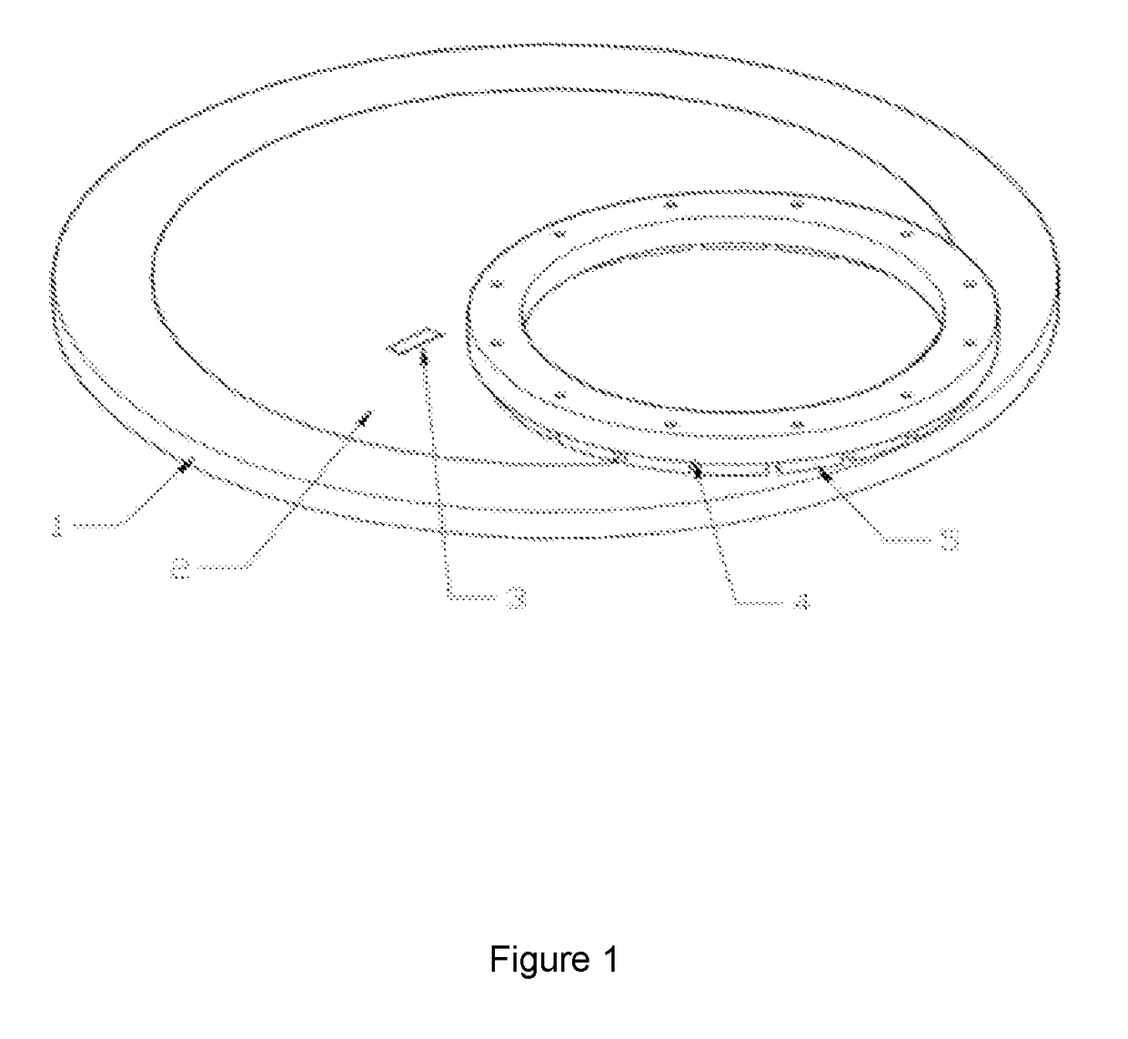
Chemical mechanical polishing pads having a consistent pad surface microtexture
a technology of chemical mechanical polishing and microtexture, which is applied in the direction of lapping tools, metal-working equipment, abrasive surface conditioning devices, etc., can solve the problems of limited ability to achieve a consistent microtexture of the pad surface, continuous wear of the skiver blade, and unreliable skiving process
- Summary
- Abstract
- Description
- Claims
- Application Information
AI Technical Summary
Benefits of technology
Problems solved by technology
Method used
Image

Examples
example 1
[0062]Trials were conducted with two versions of a VP5000™ CMP polishing layer or pad (Dow Chemical, Midland, Mich. (Dow)) having a 330 mm (13″) radius. The pads had no windows. In Example 1-1, the CMP polishing layer comprised a single porous polyurethane pad which was 2.03 mm (80 mil) thick, and wherein the polyurethane had a Shore D hardness of 64.9. In Example 1-2, the CMP polishing layer comprised a stacked pad having the same polyurethane pad of Example 1-1 stacked using a pressure sensitive adhesive onto a SUBA IV™ sub-pad made from polyester felt (Dow).
[0063]The Comparatives in Examples 1-A and 1-B were the same pads, respectively, as in Examples 1-1 and 1-2, but not treated in accordance with the methods of the present invention: The stacked pad had a SIV sub-pad.
[0064]All pads had 1010 grooves (a concentric circle groove pattern with 0.0768 cm (0.030″) deep×0.0511 cm (0.020″) wide×0.307 cm (0.120″) pitch), and no window.
[0065]The porous abrasive material was a vitrified, p...
example 2
[0074]Trials were conducted with a large 419 mm (16.5″) radius IC1000™ single layer polyurethane pads (Dow) having a Shore D hardness at 61.0, with the Example 2 pad treated in the manner as in Example 1 above, except that the rotary grinder assembly was fed down towards the flat bed platen at a rate of 20.3 μm (0.0007″) increments every 8 pad revolutions and grinding was continued for 5.5 min. The Comparative Example 2-A pad was the same pad as in Example 2 not treated in accordance with the methods of the present invention.
[0075]Trials were run on 14 pads and average results are reported for thickness variation, which was tested, as follows:
[0076]Thickness Variation:
[0077]Was determined using a coordinate-measurement machine across the surface of the polishing pads. A total of 9 discrete measurement locations from pad center to edge were collected per pad. Thickness variation was calculated by subtracting the thinnest measurement from the thickest measurement. Results are shown in...
example 3
[0082]Trials were conducted with large 419 mm (16.5″) radius IK2060H™ single layer polyurethane pads (Dow) having a Shore D hardness at 33.0, with the Examples 3-1, 3-2, 3-3 pads treated in the manner as in Example 2, above, except that the rotary grinder assembly was fed down towards the flat bed platen and stopped at different heights to achieve light (least grinding, stopped after removing 12.7 μm (0.5 mil) of the pad as measured from the highest peak on the pad surface at which the grinding surface first contacts the pad), medium (stopped after removing 50.8 μm (2 mil) of the pad as measured from the highest peak on the pad surface), and full surface microtexturing (most grinding, stopped after removing 101.6 μm (4 mil) of the pad as measured from the highest peak on the pad surface). The Comparative Example 3-A pad was the same pad as in Example 3-1, 3-2, and 3-3 but was not treated in accordance with the methods of the present invention.
[0083]All pads had 1010 grooves (a conce...
PUM
 Abstract
Description
Claims
Application Information