
Magnetooptic recording medium and reproducing method therefor

A recording medium, opto-magnetic technology, applied in the direction of magnetic recording, combined recording, data recording, etc., can solve the problems of small reproduced signal, limited length, unable to prevent overlapping signals, etc.

Inactive Publication Date: 2004-05-26
HITACHT MAXELL LTD
View PDF4 Cites 0 Cited by
  • Summary
  • Abstract
  • Description
  • Claims
  • Application Information

AI Technical Summary

Problems solved by technology

[0008] Although tiny magnetic domains can be regenerated by DWDD, there is a problem that the regenerated signal is small, and the size of the signal is only the minimum for correct reproduction.
After adding the intermediate layer, although it can prevent overlapping of short magnetic marks, CARED, like DWDD, cannot prevent overlapping signals for long magnetic marks.
Therefore, in the recording and reproducing device, it can only be applied to a signal processing system with a limited length.

Method used


Image

  • Magnetooptic recording medium and reproducing method therefor
  • Magnetooptic recording medium and reproducing method therefor
  • Magnetooptic recording medium and reproducing method therefor

Examples


Embodiment 1

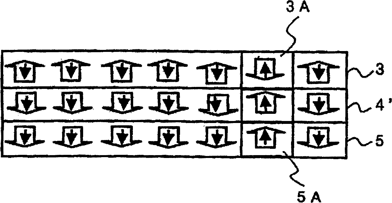
[0129] This example is made as Figure 20 A magneto-optical disk 300 of the structure shown. The magneto-optical disk 300 corresponds to the first type of magneto-optical recording medium of the present invention. The magneto-optical disk 300 is provided with a dielectric layer 2, an expansion reproduction layer (magnetic domain expansion reproduction layer) 3, an expansion activation layer 4′, a recording layer 5, a protective layer 7, a heat dissipation layer 8 and a protective coating 9 on a substrate 1. Such a magneto-optical recording medium 300 was manufactured using a high-frequency sputtering apparatus as follows.

[0130] Substrate 1 is used as Figure 21 Polycarbonate substrates of the shape shown. The substrate 1 has a track pitch TP=700nm, a land half-width value L=200nm, a groove half-width value G=500nm, a groove depth D=60nm and a thickness of 0.6mm. The land half-width value L and the groove half-width value G respectively represent the widths of the land a...

Embodiment 2

[0139] A plurality of magneto-optical disk samples were produced in the same manner as in Example 1 except that the enlarged reproduction layer 3 of the magneto-optical disk was changed to various thicknesses of 10 to 15 nm. Bit error rate (BER) measurement was performed on these magneto-optical disks as in Example 1. The relationship between the various film thicknesses t of the enlarged reproduction layer 3 and the measured bit error rate is as follows: Figure 31 shown. Depend on Figure 31 It can be seen that when the film thickness t of the enlarged reproduction layer 3 is in the range of 15-30 nm, the error rate is 1×10 -4 . This is because if the thickness of the enlarged reproduction layer 3 is thinner than the above range, the recording magnetic domains of the enlarged trigger layer and the recording layer will be seen through the reproduction layer, making accurate signal reproduction difficult. On the other hand, when the film thickness of the expanded reproduct...

Embodiment 3

[0141] This example is about the method of obtaining the magnitude of the exchange coupling magnetic field (exchange coupling force) acting between the enlarged reproduction layer and the recording layer of the magneto-optical disk produced in Example 1. The exchange bonding force can be obtained by measuring the magnetic field dependence of the magneto-optical Kerr effect from the enlarged reproduction layer side. Figure 25 Shown is the hysteresis curve of the magneto-optical disk of Example 1 at room temperature. This hysteresis curve is obtained by injecting measurement light from the enlarged reproduction layer side and measuring the magnetic field dependence of the polar magneto-optical Kerr rotation angle. On the enlarged reproduction layer, the information recording layer with a large coercive force acts to exchange the combined magnetic field, and the hysteresis curve is shifted to the left side (negative magnetic field side). This offset corresponds to the exchange ...


PUM

PropertyMeasurementUnit
Curie pointaaaaaaaaaa
thicknessaaaaaaaaaa

Abstract

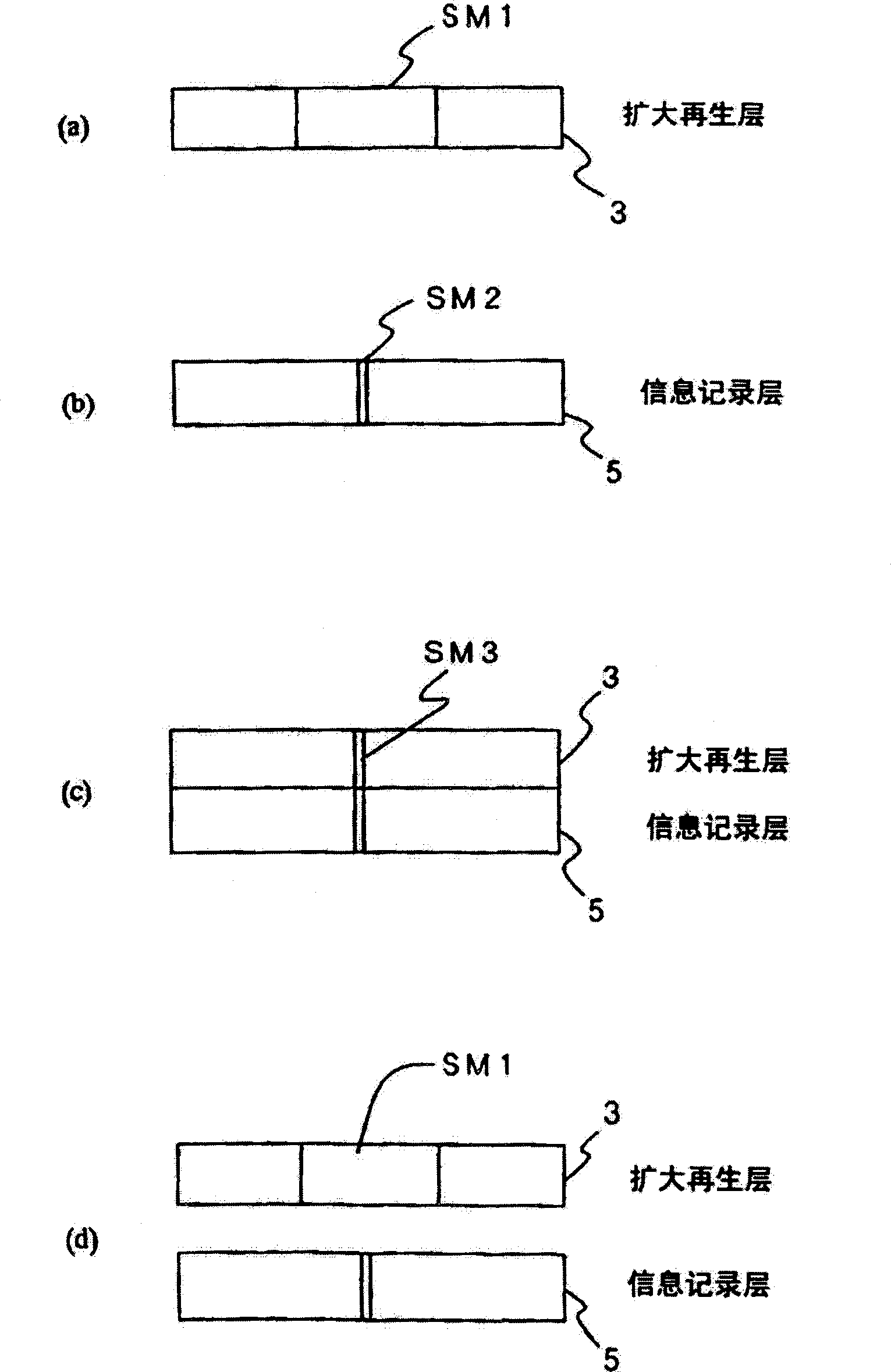
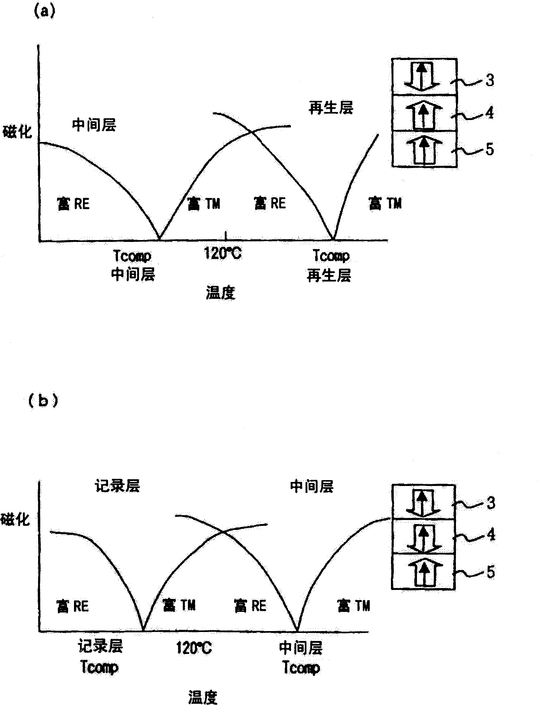
The present invention relates to a magneto-optical recording medium and reproduce method, in particular, a magneto-optical recording medium and reproduce method, which reproducing a high recording density information with a reliable and sufficient reproducing signal intensity. A magneto-optical recording medium comprises a recording layer 5, an intermediate layer 4, and a reproducing layer 3. The reproducing layer 3 is formed of a rare earth transition metal alloy in which rare earth metal is dominant, and each of the intermediate layer 4 and the recording layer 5 is formed of a rare earth transition metal alloy in which transition metal is dominant. The intermediate layer 4 exhibits in-plane magnetization at a temperature of not less than 140 DEG C. Therefore, the intermediate layer 4 cuts off the exchange coupling force between the recording layer 5 and the reproducing layer 3 during the reproduction. A magnetic domain 3A, which is transferred to the reproducing layer 3, is expanded to a size of a minimum magnetic domain diameter by the magnetostatic repulsive force exerted between the magnetic domain in the intermediate layer 4 and the magnetic domain in the reproducing layer. It is possible to obtain a reproduced signal having an amplified intensity without generating any ghost signal by the magnetic domain expansion reproduction.

Description

technical field [0001] The present invention relates to a magneto-optical recording medium and its reproduction method, in particular to a magneto-optic recording medium capable of reproducing high-density recorded information with reliable and sufficient reproduction signal strength and its reproduction method. Background technique [0002] Due to the development of the information society, the storage density of external storage devices for storing huge amounts of information has been significantly increased. The same is true for medium-replaceable optical disks. Research on densification by reducing the spot size by blue lasers and by high-NA lenses is becoming more and more popular. However, at this stage, it is difficult to provide blue lasers in large quantities and at low cost, so it is expected to use red lasers and other technologies to achieve large capacity. This technology is applicable when blue laser light becomes available in large quantities in the future, t...

Claims


Application Information

Patent Timeline
Patent Type & Authority Applications(China)
IPC IPC(8): G11B11/105
CPCG11B11/10584G11B11/10515G11B11/10593
Inventor 粟野博之关根正树谷学今井奖井上和子铃木芳和国府田安彦石崎修岛崎胜辅
Owner HITACHT MAXELL LTD
Learn More