Organic electroluminescent cell

An electroluminescence component, an organic technology, applied in the direction of electrical components, electroluminescence light sources, electric light sources, etc., can solve the problems of limited improvement of brightness and luminous efficiency, failure to achieve brightness, etc., and achieve the combination of increased probability and luminous efficiency The effect of boosting and attenuation rate improvement

Inactive Publication Date: 2004-06-16
RITDISPLAY
View PDF0 Cites 5 Cited by
  • Summary
  • Abstract
  • Description
  • Claims
  • Application Information

AI Technical Summary

Problems solved by technology

Moreover, generally, phosphorescent materials are used as components of the light-emitting layer and cannot achieve the desired brightness at lower voltages.
[0007] (2) Doping the phosphorescent material (Guest) in other luminescent material (Host) at a ratio of 1% to 10% as a light-emitting layer, and using the luminescent material (Host) to generate energy transfer (energytransfer) to make the phosphorescent material (Guest) Luminous, its color coordinates will also change as the brightness rises, this method has very limited improvement in brightness and luminous efficiency

Method used


Image

  • Organic electroluminescent cell
  • Organic electroluminescent cell
  • Organic electroluminescent cell

Examples


Embodiment Construction

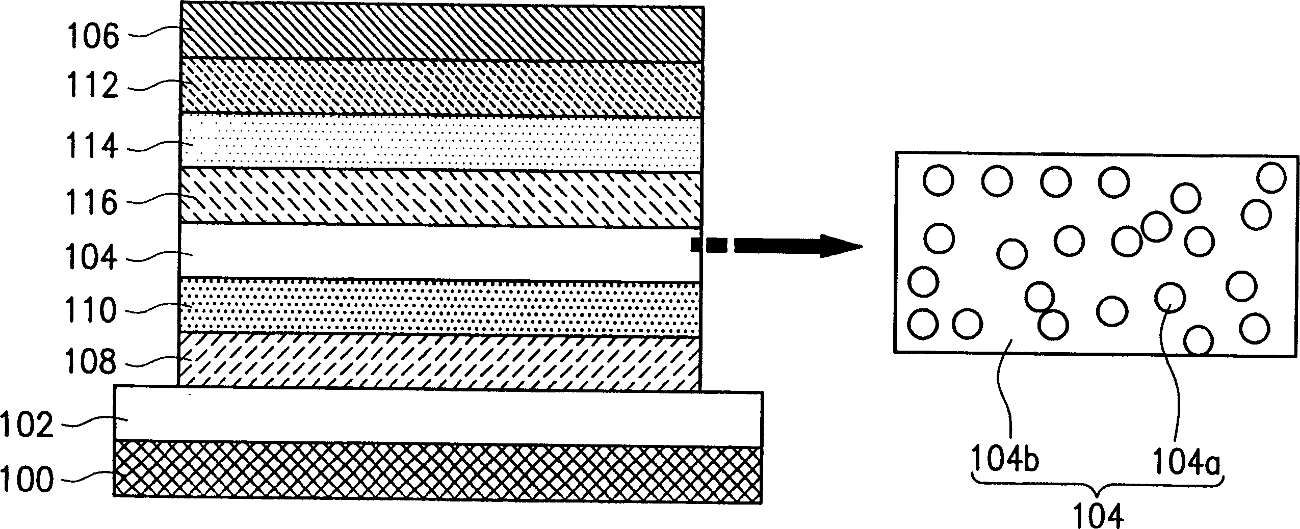
[0016] The principles and features of the organic electroluminescence element of the present invention will be described in detail below with reference to the accompanying drawings.

[0017] In the general electroluminescence mechanism, there are two ways to present light, one is that the excited state electron spin structure is a singlet state (Singlet), and the other is that the excited state electron spin structure is a triplet state (Triplet). When the excited state electron spin structure is a singlet state, the released light is called Fluorescence, and its structure is:

[0018] S1→S0+hv

[0019] When the excited state electron spin structure is a triplet state, the released light is called phosphorescence (Phosphorescence), and its structure is:

[0020] T1→S0+hv

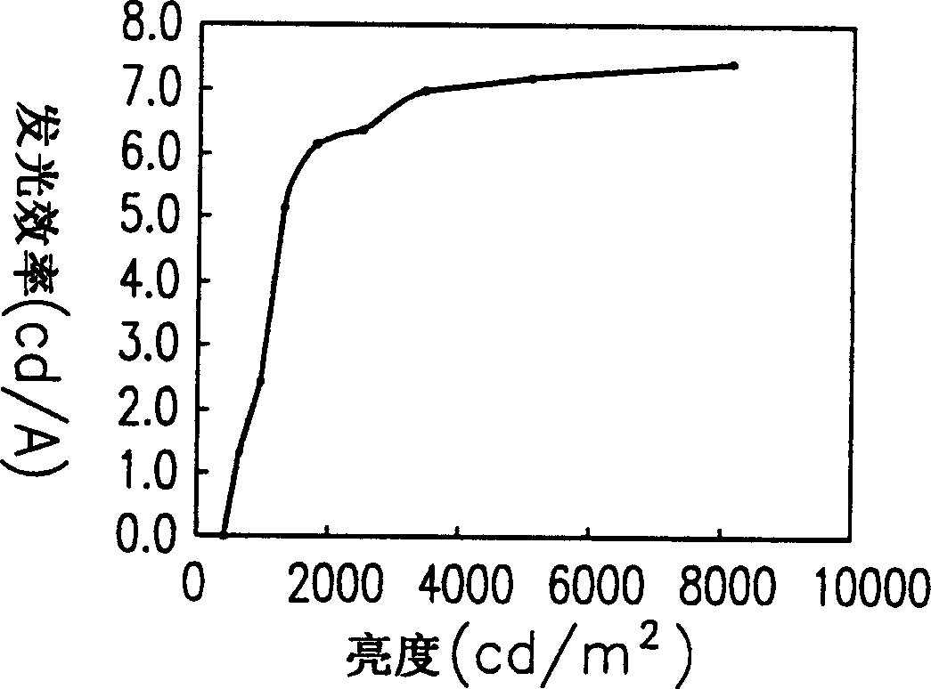
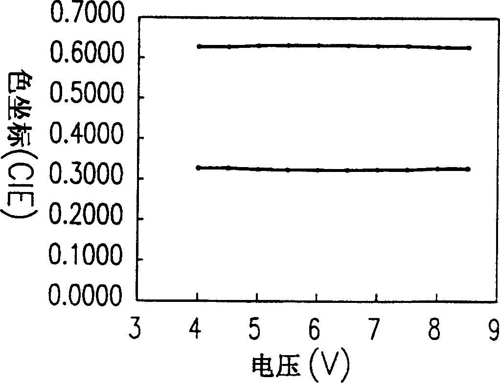
[0021] The external quantum efficiency of electroluminescence ψEL=xψfηrηe. Among them, x is the electron spin quantum number of the excited state; ψf is the efficiency of charge injection into the light-e...


PUM


Abstract

The invention is a kind of organic electricity laser illuminating element, which is mainly made up of base board, positive layer, illuminating layer, and cavity resistant layer. The positive layer is set on the base board; the illuminating layer is set on the positive layer; the cavity resisting layer is set on the illuminating layer; the negative layer is set in the cavity resistant layer. The illuminating layer is organic material mixed with cavity conduction material and phosphorescence material, the density of the two materials is between forty percentages to sixty percentages.

Description

technical field [0001] The invention relates to an organic electroluminescence element (OLED), in particular to an organic electroluminescence element in which a hole-conducting material and a phosphorescent material are doped into an organic material as a light-emitting layer. Background technique [0002] The information and communication industry has become the mainstream industry today, especially the development of various portable communication display products, and the flat panel display is particularly important as an interface for people to communicate information. The technologies currently applied to flat-panel displays mainly include the following: plasma display (Plasma Display Panel, PDP), liquid crystal display (LiquidCrystal Display, LCD), inorganic electroluminescent display (Electro-luminescentDisplay), light-emitting diode array display (Light Emitting Diode (LED), Vacuum Fluorescent Display (Vacuum Fluorescent Display), Field Emission Display (Field Emiss...

Claims


Application Information

Patent Timeline
Patent Type & Authority Applications(China)
IPC IPC(8): H05B33/14H05B33/26
Inventor 李勇志陈维恕廖启智李君浩
Owner RITDISPLAY
Why Eureka
Try Eureka