

Excimers lamp
An excimer lamp, inner tube technology, applied in discharge lamps, discharge tubes, electrical components, etc., can solve the problems of uneven brightness, decreased brightness, increased bulb intensity, etc., to suppress generation and expansion, and prolong life. Effect
- Summary
- Abstract
- Description
- Claims
- Application Information
AI Technical Summary
Problems solved by technology
Method used
Image

Examples
no. 1 example
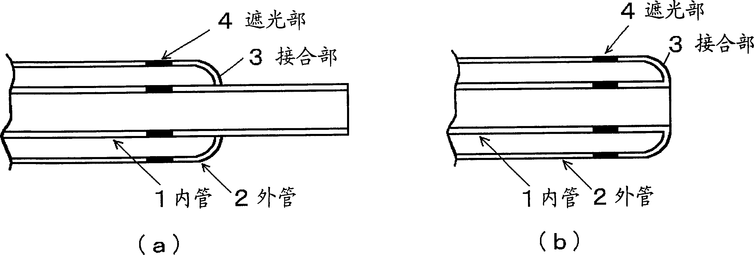
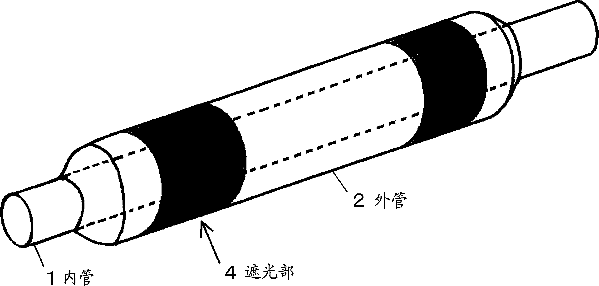
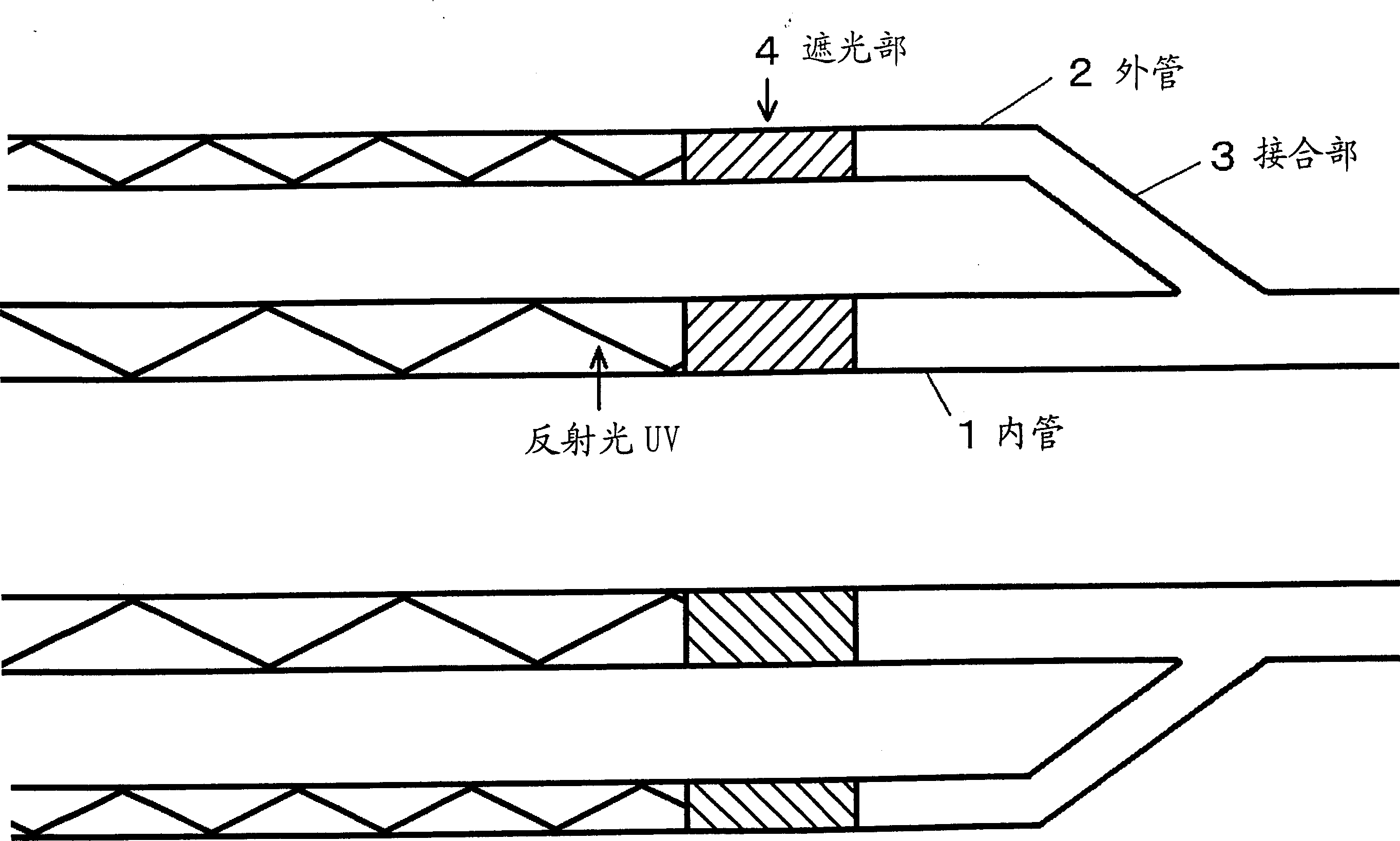
[0024] The first embodiment of the present invention is an excimer lamp in which a light-shielding portion for absorbing or scattering ultraviolet rays is provided on the tube body of the inner tube and the outer tube between the effective light-emitting portion and the joint portion.
[0025] figure 1 is a cross-sectional view of the excimer lamp according to the first embodiment of the present invention. figure 1 (a) is an excimer lamp of a type with a long inner tube. figure 1 (b) is an excimer lamp of the type in which the inner tube and the outer tube have equal lengths. exist figure 1 In, the inner tube 1 is the inner quartz glass tube. The outer tube 2 is the outer quartz glass tube. The joint part 3 is a part for joining the inner tube and the outer tube. The space formed by the inner tube and the outer tube is the discharge space. Discharge gas is sealed in the discharge space. The light shielding portion 4 is glass for shielding or scattering ultraviolet r...
no. 2 example
[0031] A second embodiment of the present invention is an excimer lamp in which a hardening agent is coated at the junction of an inner tube and an outer tube.
[0032] Figure 4 is a cross-sectional view of an excimer lamp according to a second embodiment of the present invention. Figure 4 (a) is an excimer lamp of a type with a long inner tube. Figure 4 (b) is an excimer lamp of the type in which the inner tube and the outer tube have equal lengths. exist Figure 4 In, the inner tube 1 is the inner glass tube. The outer tube 2 is the outer glass tube. The joint part 3 is a part for joining the inner tube and the outer tube. The curing agent 5 is a curing agent such as an adhesive.
[0033] Now, the function of the excimer lamp according to the second embodiment of the present invention constituted as above will be described. like Figure 4 As shown, a curing agent 5 such as an adhesive material is applied to the outer surface of the double-tube bulb other than the ...
no. 3 example
[0037]The third embodiment of the present invention is that a light-shielding part for absorbing or dispersing ultraviolet rays is provided between the outer tube and the inner tube between the effective light-emitting part and the joint part, and a hardening agent is coated on the joint part. Excimer lamps.
[0038] Figure 5 is a cross-sectional view of an excimer lamp according to a third embodiment of the present invention. Figure 5 (a) is an excimer lamp of a type with a long inner tube. Figure 5 (b) is an excimer lamp of the type in which the inner tube and the outer tube have equal lengths. exist Figure 5 In, the inner tube 1 is the inner glass tube. The outer tube 2 is the outer glass tube. The joint part 3 is a part for joining the inner tube and the outer tube. The light shielding portion 4 is glass for shielding ultraviolet rays. The curing agent 5 is a curing agent such as an adhesive.
[0039] Now, the function of the excimer lamp according to the third...
PUM
| Property | Measurement | Unit |
|---|---|---|
| Outer diameter | aaaaa | aaaaa |
Abstract
Description
Claims
Application Information