Charging circuit for secondary battery
一种备用电池、充电电路的技术,应用在电池电路装置、电路装置、集电器等方向,能够解决输入偏置电压不能被忽略、检测充电电流精度变低、不可能备用电池充电等问题,达到限制电路尺寸增加、减少检测错误、增加灵活性的效果
- Summary
- Abstract
- Description
- Claims
- Application Information
AI Technical Summary
Problems solved by technology
Method used
Image
Examples
no. 1 example
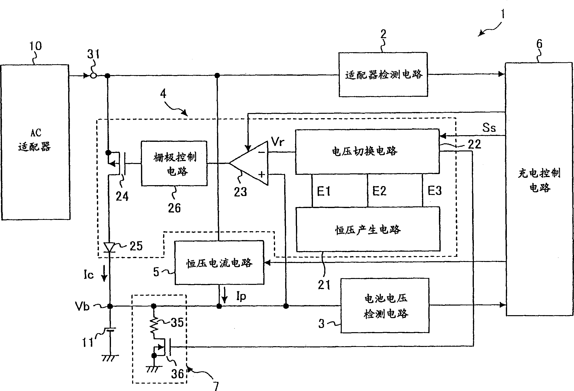
[0052] figure 1 A structural diagram of a charging circuit for a backup battery according to the first embodiment of the present invention is shown. have to be aware of is, figure 1 An example of a charging circuit for a lithium-ion battery of a mobile phone is shown.
[0053] exist figure 1 Among them, the charging circuit 1 of the backup battery includes: an adapter detection circuit 2 for outputting a predetermined signal when the power supply voltage from an AC adapter 10 as a DC power supply is equal to or greater than a predetermined value; a battery voltage detection circuit 3 for detecting and Outputting a positive voltage Vb (hereinafter referred to as "battery voltage") Vb of a lithium ion battery 11 used as a backup battery; and a constant voltage circuit 4 for charging the lithium ion battery 11 at a constant voltage.
[0054] In addition, the charging circuit 1 includes: a constant current circuit 5 for pre-charging the lithium-ion battery 11 with a predeter...
no. 2 example
[0082] Fig. 5 shows a charging circuit according to a second embodiment of the present invention. In Fig. 5, the charging circuit includes: AC adapter B10 for providing charging current; adapter detection circuit 12 for detecting the connection of AC adapter B10; battery voltage detection circuit 16 for detecting the voltage of backup battery 14; constant voltage The circuit 18 is used to perform constant voltage charging on the backup battery 14; the constant current circuit 20 is used to provide a constant current to the backup battery 14; the gate voltage detection circuit B22 is used to detect the voltage of the control terminal of the control transistor M1; the diode D1 , for preventing current from flowing into the AC adapter B10 from the backup battery B24; and a charge control circuit B24 for performing drive control of the constant voltage circuit 18 and the constant current circuit 20. An AC adapter B10 is connected to terminal 30 . The constant voltage circuit 18 i...
no. 3 example
[0094] Figure 8 A charging circuit diagram of the backup battery 14 according to the third embodiment of the present invention is shown. exist Figure 8 In , the same components as those corresponding to those in FIG. 5 are denoted by the same reference numerals, and descriptions thereof are omitted. The charging circuit according to the third embodiment includes, in addition to the charging circuit shown in FIG. 5 : a current control circuit 50 for controlling the charging current output from the pMOS transistor M1 ; and a load resistor R2 . In addition, a diode D3 is connected between the operational amplifier A1 of the constant voltage circuit 18 and the pMOS transistor M1. The current control circuit 50 includes a constant voltage generating circuit 46 , an operational amplifier A4 and a diode D2 . One end of the load resistor R2 is grounded, and the other end is connected to the gate terminal of the pMOS transistor M1.
[0095] Figure 9A , 9B, and 9B respectively s...
PUM
 Abstract
Description
Claims
Application Information
 - R&D
- Intellectual Property
- Life Sciences
- Materials
- Tech Scout
- Unparalleled Data Quality
- Higher Quality Content
- 60% Fewer Hallucinations
Browse by: Latest US Patents, China's latest patents, Technical Efficacy Thesaurus, Application Domain, Technology Topic, Popular Technical Reports.
© 2025 PatSnap. All rights reserved.Legal|Privacy policy|Modern Slavery Act Transparency Statement|Sitemap|About US| Contact US: help@patsnap.com


