Position measuring method, system and device and radio device in organism

A technology of a wireless device and a measurement method, which can be applied to measurement devices, radio wave measurement systems, positioning and other directions, and can solve problems such as large burden on living organisms

Inactive Publication Date: 2004-08-04
NTT DOCOMO INC
View PDF0 Cites 10 Cited by
  • Summary
  • Abstract
  • Description
  • Claims
  • Application Information

AI Technical Summary

Problems solved by technology

However, when the camera is transported to a predetermined part of the living body, the cable connected to the camera is guided into the body, thereby imposing a large burden on the living body

Method used


Image

  • Position measuring method, system and device and radio device in organism
  • Position measuring method, system and device and radio device in organism
  • Position measuring method, system and device and radio device in organism

Examples


Embodiment 1

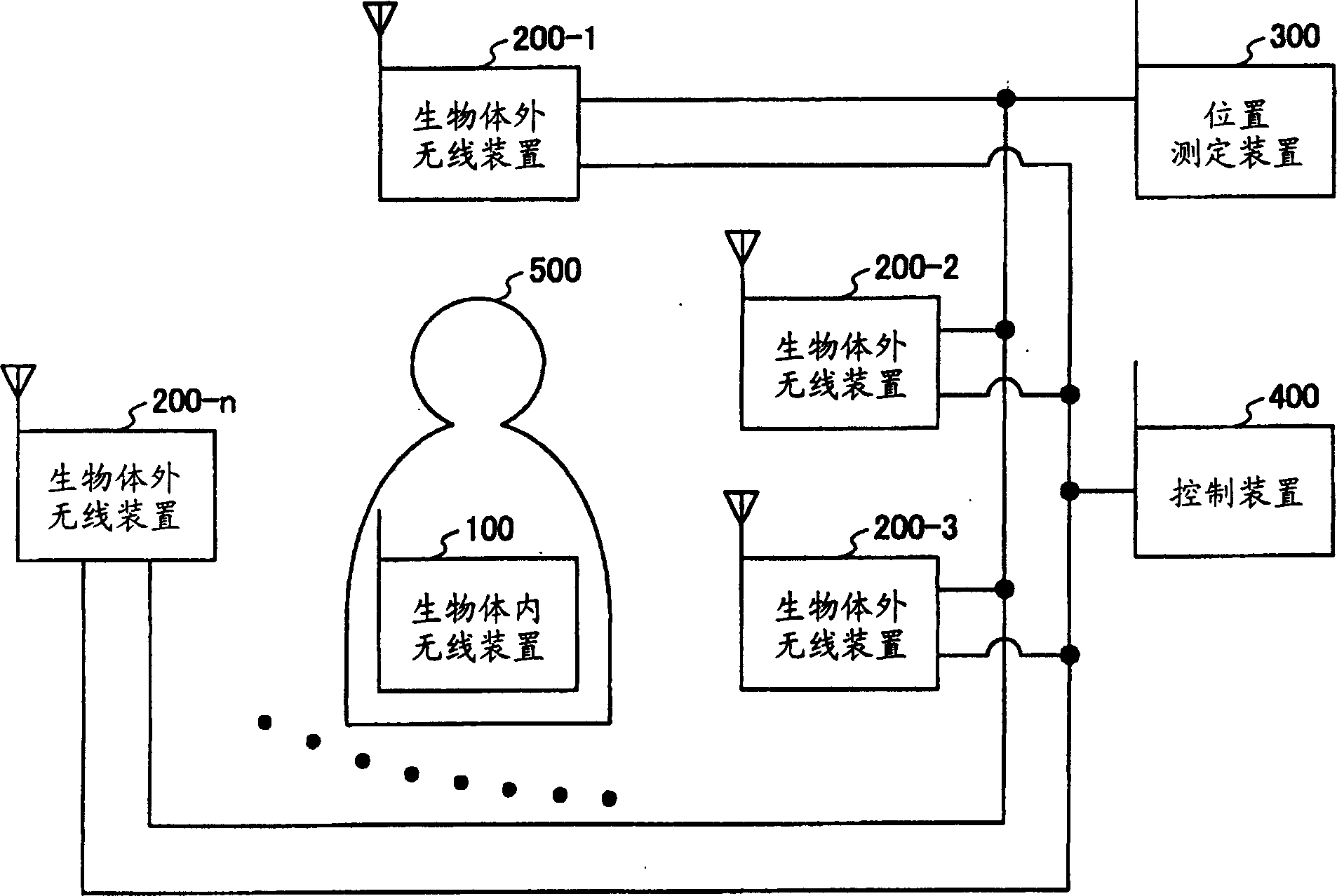
[0033] figure 1 It is a diagram showing a configuration example of the position measurement system in the first embodiment. The position measuring system shown in this figure is composed of the following parts: an in vivo wireless device 100, which is placed in a living body 500; -1 to 200-n are appropriately collectively referred to as "extra-body wireless device 200"), which are arranged outside the living body 500; the position measuring device 300; and the control device 400.

[0034] In the position measuring system in Embodiment 1, each in vitro wireless device 200 receives a signal transmitted from the in vivo wireless device 100, and the position measuring device 300 measures the position of the in vivo wireless device 100 based on the reception status.

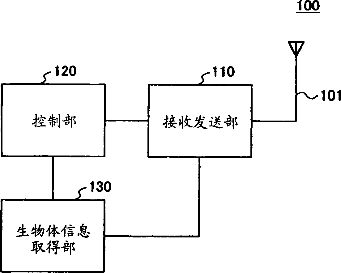
[0035] figure 2 It is a diagram showing a configuration example of the in vivo wireless device 100 in the first embodiment. The in vivo wireless device 100 shown in the figure includes an antenna 101 , a transmis...

Embodiment 1-1

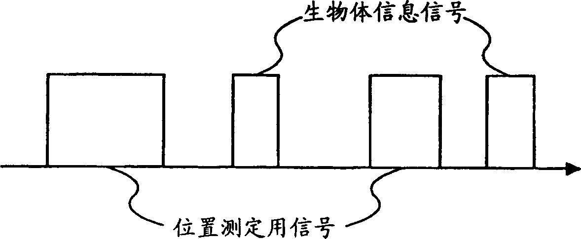
[0042] In the present embodiment, the position measuring device 300 measures the position of the in-vivo wireless device 100 based on the difference in the signal reception times of the respective in-body wireless devices 200 . Specifically, when the transmitting / receiving unit 110 in the in vivo wireless device 100 transmits a biological information signal or a signal for position measurement, the current time, that is, the time at the time of transmission (hereinafter referred to as "transmission time") is included in these signals. Send within the signal. When the receiving and transmitting unit 210 in each in vitro wireless device 200 receives a biological information signal or a signal for position measurement, it includes the current time, that is, the time at the time of reception (hereinafter referred to as "reception time") in these signals and transmits the signal. to the position measuring device 300 . The transmitting / receiving unit 310 in the position measuring d...

Embodiment 1-2

[0053] In the present embodiment, the position measurement device 300 measures the position of the in-vivo wireless device 100 based on the phase difference of the signals received by each of the in-body wireless devices 200 . Specifically, the position measurement unit 320 in the position measurement device 300 uses the wavelength λ of the biological information signal or the signal for position measurement and the position p of the wireless device 100 in the living body. 0 , and the position p of the i-th in vitro wireless device 200 i , use the following formula 3 to obtain the reception phase φ of the biological information signal or the signal for position measurement received by the i-th in vitro wireless device 200 i .

[0054] [Formula 3]

[0055] φ i = 2 π λ ( | | p 0 ...


PUM


Abstract

A system for measuring the position of an in vivo radio device is disclosed. The system comprises the in vivo radio device (100) administered into a living organism, a plurality of in vitro radio devices (200-1,200-2,...) disposed outside of the living organism, and a position measuring device (300). The in vivo radio device includes a transmitter for transmitting a vital information signal or a position measuring signal. Each of the in vitro radio devices includes a receiver for receiving the vital information signal or the position measuring signal. The position measuring device includes a position measuring unit for measuring the position of the in vivo radio device based on receiving characteristics of the vital information signal or the position measuring signal received by the in vitro radio devices.

Description

technical field [0001] The present invention relates to a position measurement method for measuring the position of an in vivo wireless device inserted into a living body, a position measurement system using the position measurement method, a position measurement device, and an in vivo wireless device. Background technique [0002] Non-Patent Document 1: December 19, 2014 Via the Internet URL: http: / / www.rfnorika.com / norikapl.html "RF robot ツ ト カプセル endoscope" found online [0003] Conventionally, an endoscope has been used as a medical device that acquires information in a living body outside the living body. This endoscope has a configuration in which a camera is attached to the tip of a cable. The camera takes an image of a predetermined part (for example, an affected part) in a living body. The captured image is transmitted by the cable and displayed on the monitoring device outside the living body. However, when the camera is delivered to a predetermined part of the...

Claims


Application Information

Patent Timeline
Patent Type & Authority Applications(China)
IPC IPC(8): A61B1/00A61B5/00A61B5/06G01S5/04G01S5/06
CPCA61B5/06A61B1/041A61B5/0031A61B5/062
Inventor 福田敦史垂泽芳明寺田矩芳
Owner NTT DOCOMO INC
Why Eureka
Try Eureka