
Acceleration earthquake sensor

A seismic sensor and acceleration technology, which is applied in the direction of seismic signal receivers, etc., can solve the problems of inability to translate, weak overload protection capability, large sensor linearity and temperature drift performance errors, etc., and achieves high working reliability and strong overload protection capability. , good linearity and temperature drift performance

Inactive Publication Date: 2004-10-20
WEIHAI SUNFULL GEOPHYSICAL EXPLORATION EQUIP
View PDF0 Cites 8 Cited by
  • Summary
  • Abstract
  • Description
  • Claims
  • Application Information

AI Technical Summary

Problems solved by technology

The disadvantage is that the translational movement between the middle electrode and the two fixed electrodes is impossible, the linearity and temperature drift performance error of the sensor is large, and the overload protection ability is weak.

Method used


Image

  • Acceleration earthquake sensor
  • Acceleration earthquake sensor
  • Acceleration earthquake sensor

Examples


Embodiment Construction

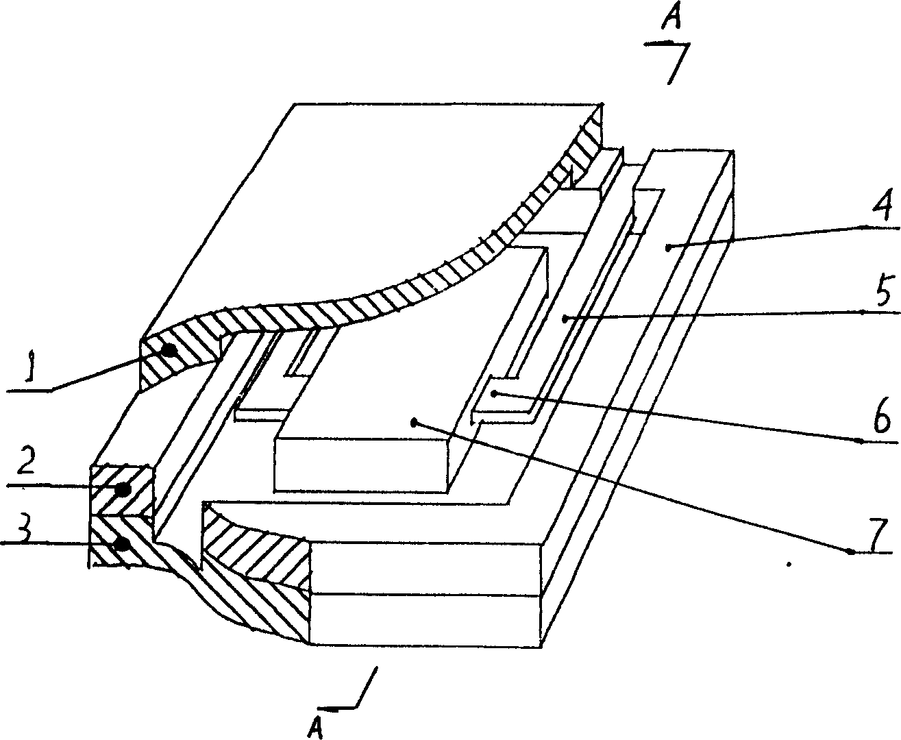
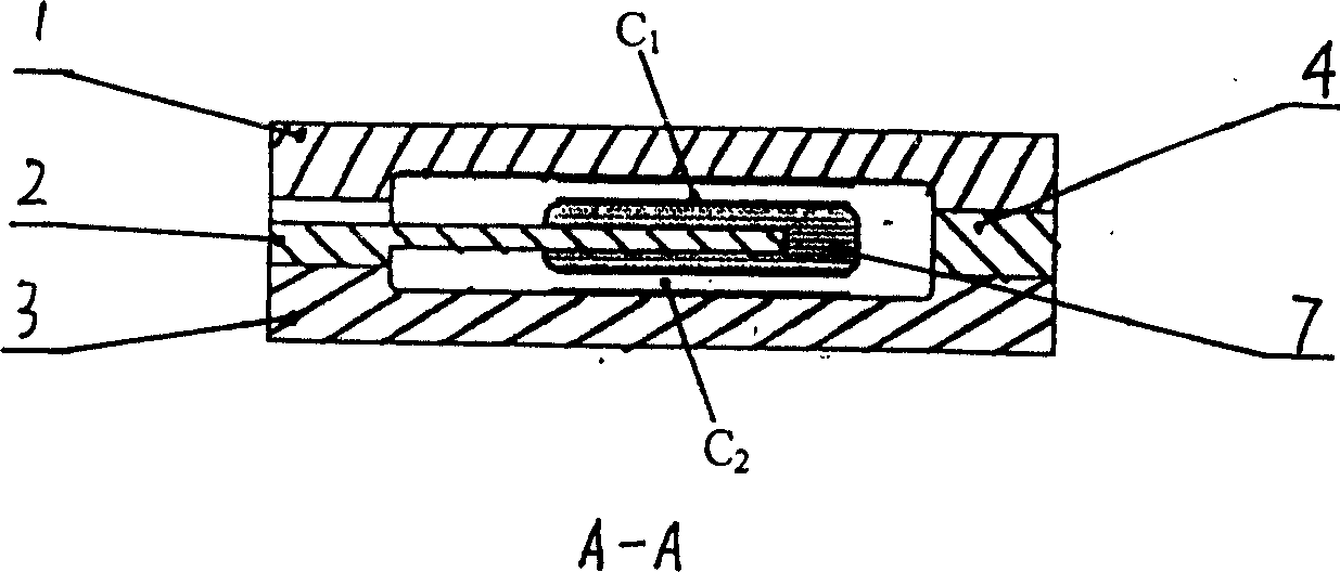
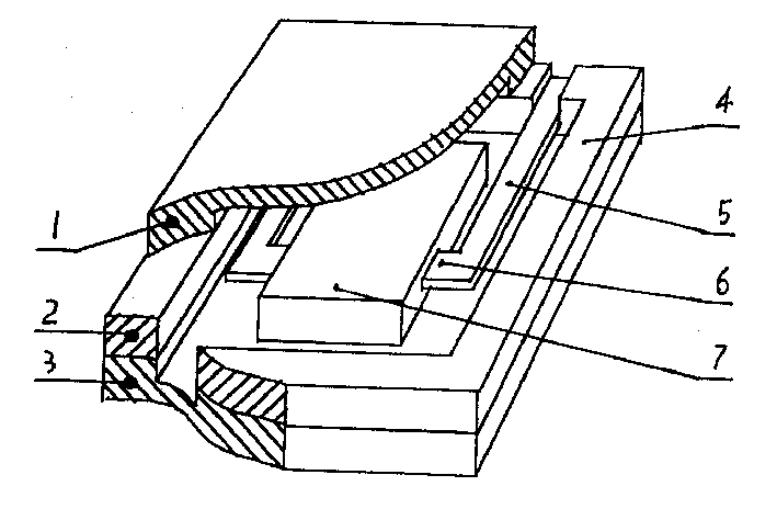
[0010] From figure 1 It can be seen that an acceleration seismic sensor includes an upper electrode 1 , a lower electrode 3 and a movable middle electrode 2 . The middle electrode 2 moves up and down under the action of acceleration, and together with the upper and lower electrodes forms a variable-pitch differential capacitor. The upper electrode 1 and the lower electrode 3 can be made of high silica glass or single crystal silicon. They are grooved electrodes formed by micromachining techniques. The upper electrode 1 and the lower electrode 3 also play the role of overload protection. The middle electrode 2 is sandwiched between the upper electrode 1 and the lower electrode 3, which is based on single crystal silicon with [100] crystal orientation, and is formed by micromachining technology, including a fixed frame 4, a mass block 7, a cantilever beam 5, An integral composite beam structure of the beam 6. The mass block 7 is supported by a composite cantilever beam compo...


PUM


Abstract

An ecceleration-type earthquake sensor is composed of upper and lower electrode with recess, and an intermediate electrode, which is composed of fixing frame, mass block, cantilever beam and transverse beam and can be horizontally moved between two fixed electrodes. Its advantages are high linearity and temp drift and compensation, and small size.

Description

technical field [0001] The invention relates to a seismic detection device, in particular to an acceleration seismic sensor. Background technique [0002] We know that geophones are an essential tool for geological exploration in petroleum and coal industries. Existing geophones mainly use magnetoelectric speed sensors, and their structure is mainly composed of shell, upper cover, lower cover, coil, shrapnel, magnet, yoke iron, electrodes, etc. The yoke iron is located at the upper and lower ends of the magnet, and the magnet and The positioning of the yoke is achieved through the concave holes on the yoke. They form a magnetic circuit device. The coil is wound around the magnet and the outside of the yoke and supported by shrapnel. When the outside world vibrates, the coil reciprocates up and down in the magnetic circuit to cut the magnetic force line. , output vibration signal. The performance of the magnetoelectric geophone mainly depends on the performance of the magne...

Claims


Application Information

Patent Timeline
Patent Type & Authority Applications(China)
IPC IPC(8): G01V1/18
Inventor 牛德芳颜永安于国良
Owner WEIHAI SUNFULL GEOPHYSICAL EXPLORATION EQUIP
Learn More