
Ink jet position regulator for making display screen

A technology of position adjustment device and inkjet head, applied in printing, optics, instruments, etc., can solve the problems of use, uneven coating thickness and width, expensive equipment, etc., to achieve simple production process, improve product quality, improve The effect of work efficiency

Inactive Publication Date: 2004-11-24
LEIJIN ELECTRONIC SHENYANG CO LTD
View PDF0 Cites 2 Cited by
  • Summary
  • Abstract
  • Description
  • Claims
  • Application Information

AI Technical Summary

Problems solved by technology

[0004] The screen printing method is a simple method with a simple process and low-cost equipment, but it is not suitable for high-precision processing due to uneven coating thickness and width.
The photolithographic printing method has good uniformity in thickness and width, is thin in thickness, and can also form a film layer, so it can be used as a high-precision processing technology. However, the materials used are expensive, the loss is large, and the manufacturing process Complicated and has the disadvantage of using expensive equipment

Method used

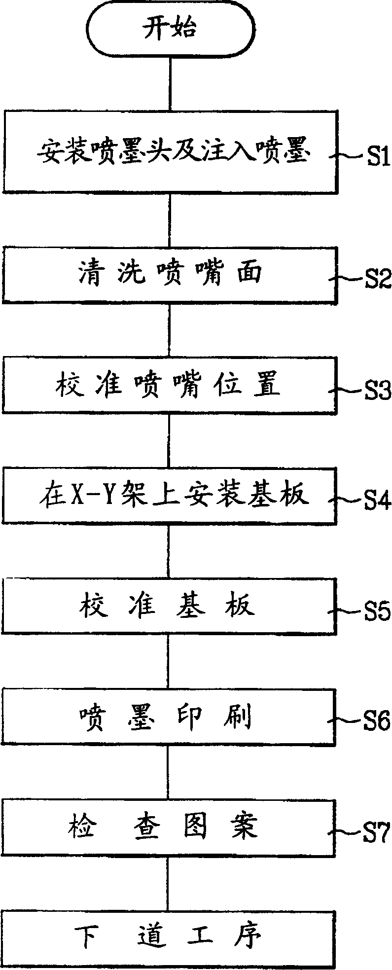

Image

  • Ink jet position regulator for making display screen
  • Ink jet position regulator for making display screen
  • Ink jet position regulator for making display screen

Examples


Embodiment Construction

[0016] according to Figure 1-3 The specific structure and working process of the present invention are described in detail with the embodiment.

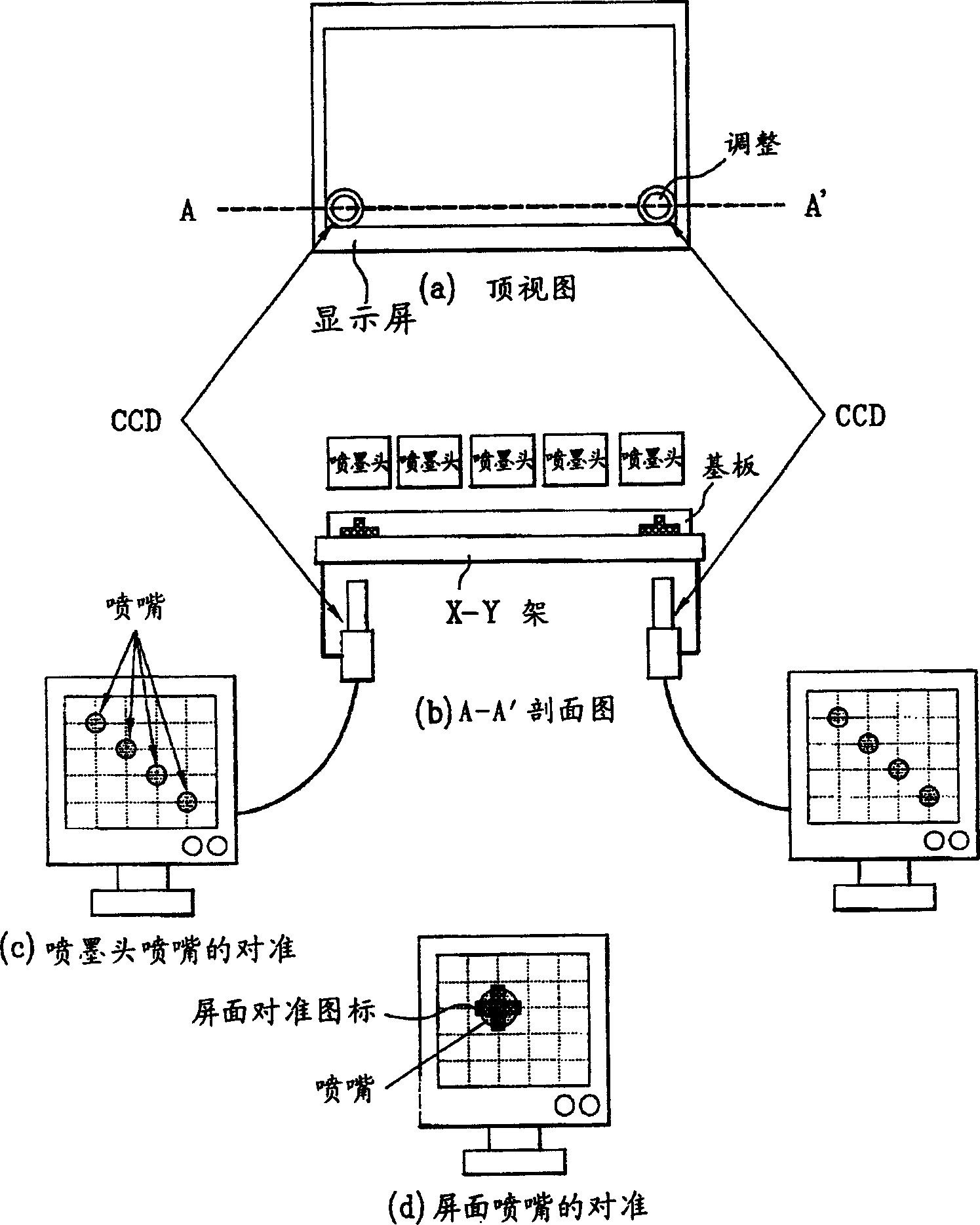
[0017] figure 1 It is a structural schematic diagram of an inkjet head position adjustment device for making display screens according to the present invention.

[0018] as in figure 1 As shown, because the nozzles of the inkjet head are facing downward, two CCD (charge coupled devices) cameras are installed on the X-Y frame from bottom to top.

[0019] Of the two CCD cameras, one or both can do image processing.

[0020] As shown in figure (a), two through holes are arranged on the X-Y frame, and two CCD cameras are respectively arranged below them.

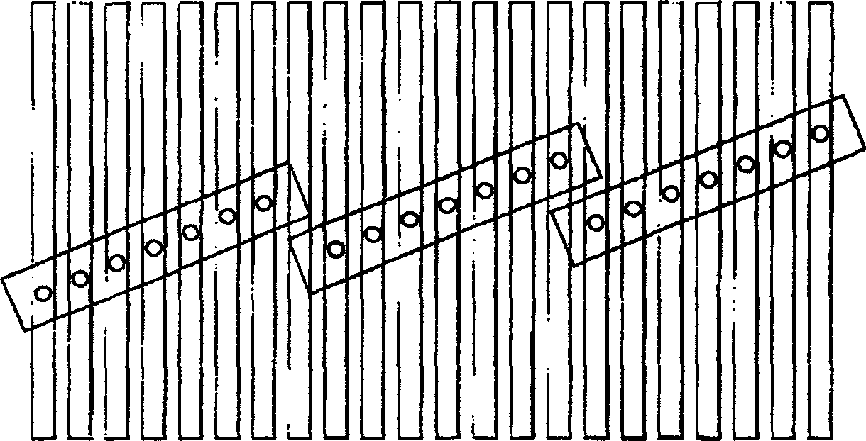
[0021] The sectional view of A-A' of figure (a) is figure (b). like image 3 As shown, in the inclined inkjet head, put the nozzle of the first inkjet head that needs to be aligned on the through hole, so as to align the grid formed by the image pixel pitch that needs to be inkj...


PUM


Abstract

The ink jet position regulator for making display screen consists of several position regulating ink jetting heads capable of aligning the jet position and several CCD cameras capable of regulating ink jetting heads to make nozzles of the ink jetting heads align to image pixel pitch formed lattice. The present invention has no demerits in traditional technology, and has simple making process, low cost, high efficiency, accurate position regulation, no double ghost in the displayed image and high product quality.

Description

technical field [0001] The invention relates to a display screen manufacturing process, in particular to a display screen manufacturing process that applies an inkjet printing method, and can align the position of the nozzles during inkjet printing with a plurality of inkjet heads. Inkjet head adjustment device. Background technique [0002] The leading product of the commonly used display screen is a CRT (cathode ray tube) called a picture tube. However, as the requirements for large-screen displays and high-definition televisions gradually increase, it is urgent to develop a CRT picture tube that is lighter and thinner, with high brightness, high efficiency, high definition, and responsiveness compared with the heavy and bulky CRT picture tube. A flat-panel display with features such as fast speed, long life, low power consumption, low price, and full color. Among the flat panel displays (FPDs) that are being developed or put into production, there are liquid crystal dis...

Claims


Application Information

Patent Timeline
Patent Type & Authority Applications(China)
IPC IPC(8): B41J2/07G02F1/13
Inventor 裴范镇文银儿赵永载孙智勋
Owner LEIJIN ELECTRONIC SHENYANG CO LTD
Learn More