Particle_optical device for object irradiation

A technology for optical devices and objects, which is applied in the direction of irradiation devices, photolithography exposure devices, microlithography exposure equipment, etc., can solve the problems of lens resonance, particle beam focusing is no longer sufficient, etc., and achieve the improvement of characteristic frequency and favorable stiffness characteristics Effect

Inactive Publication Date: 2004-12-01
FEI CO
View PDF1 Cites 6 Cited by
  • Summary
  • Abstract
  • Description
  • Claims
  • Application Information

AI Technical Summary

Problems solved by technology

Thus, for example, ambient noise or ground vibrations generated by equipment near the installation may cause the lens to resonate
Such vibrations may eventually lead to a situation where the positioning (horizontal direction) accuracy of the particle beam and / or the focusing of the particle beam on the wafer is no longer sufficient

Method used


Image

  • Particle_optical device for object irradiation
  • Particle_optical device for object irradiation
  • Particle_optical device for object irradiation

Examples


Embodiment Construction

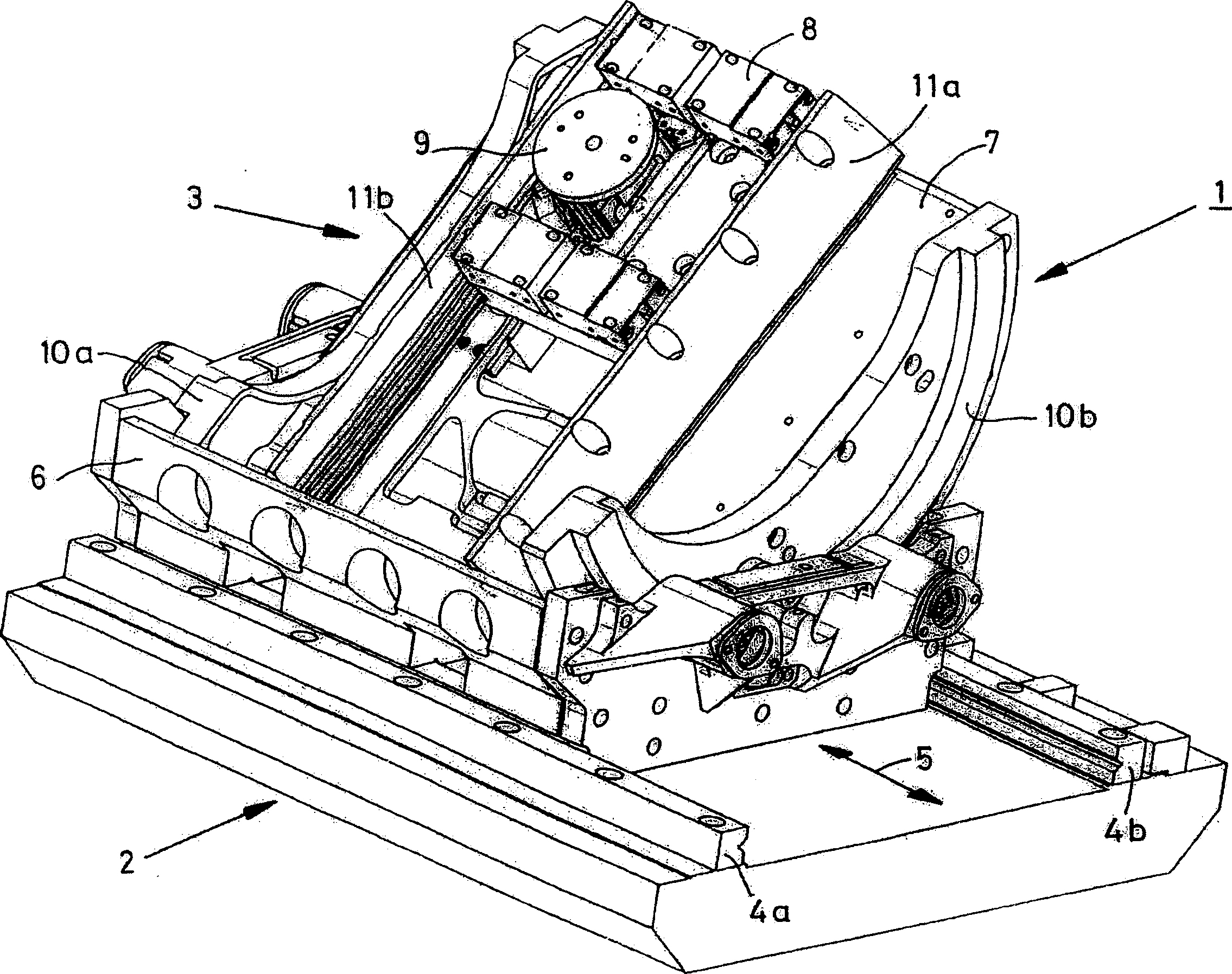
[0061] figure 1 Shown is a manipulator 1 used in a scanning electron microscope. The operating device 1 consists of a base plate 2 and an operating unit 3 . The substrate 2 is about 300 mm long and is connected to a part of the housing of the scanning electron microscope in the manner described below, see especially figure 2 . The operating device 1 weighs about 17 kg, wherein the independent operating unit 3 weighs about 7 kg, and the base plate 2 weighs about 10 kg. The manipulation unit 3 can move as a whole relative to the base plate 2 along the guide bodies 4a, 4b in the direction indicated by the double arrow 5, and the moving stroke is about 150 mm. The manipulation unit 3 includes a first moving body 6 , a rotating body 7 , a second moving body 8 and a sample holder 9 . The first moving body 6 is arranged on the opposite side of the rotating body 7 with a curved guide rail through which a correspondingly formed outer guide rib 10 formed on a part of the rotating b...


PUM


Abstract

The invention provides a particle-optical device for irradiating an object with a beam of particles. The device comprises a housing in which are located positioning means 1 for positioning the object within the housing. The positioning means comprise a reference body 2 supported against a supporting portion of the housing and a kinematic system - which can be manipulated - with an object carrier 9 for manipulating the object held in the object carrier in at least one degree of freedom with respect to the reference body 2, the device further comprising control means and at least one combination 23,30 of a piezo-electric position actuator 25 and a piezo-electric force sensor 35, which actuator and sensor are positioned in series, whereby the control means - in dependence upon at least one input signal from at least one sensor - generates a control signal for at least that actuator associated with said sensor, characterized in that the series-positioned actuators and sensors of said at least one combination are positioned between the housing and the reference body, the support of the reference body against the supporting portion of the housing occurring via said at least one combination.

Description

technical field [0001] The invention relates to a particle-optical device for radiating an object by a particle beam, which includes a housing, and a positioning device is arranged in the housing for positioning the object in the housing, and the positioning device includes: a reference body carried on a support portion of said housing; and a kinematic system capable of being manipulated and having an object carrier for maintaining relative to said reference body in at least one degree of freedom The object on the object carrier is manipulated, the particle-optical device further includes a control device and at least one combination of a piezoelectric position actuator and a piezoelectric force sensor, the actuator and the sensor are arranged in series, thereby The control means generates a control signal for at least an actuator associated with at least one sensor in dependence on at least one input signal from at least one sensor. Background technique [0002] The combin...

Claims


Application Information

Patent Timeline
Patent Type & Authority Applications(China)
IPC IPC(8): G21K5/00G21K5/04H01J37/16H01J37/20
CPCH01J37/20
Inventor A·维斯彻尔
Owner FEI CO
Why Eureka
Try Eureka