Supercharge Your Innovation With Domain-Expert AI Agents!

Turbocharger comprising a torsional-vibration damper

A technology of torsional vibration and supercharger, applied in the direction of rotation vibration suppression, engine function, engine components, etc., can solve problems such as power loss, and achieve good cooling effect

Inactive Publication Date: 2004-12-15
ABB TURBO SYST
View PDF0 Cites 5 Cited by
  • Summary
  • Abstract
  • Description
  • Claims
  • Application Information

AI Technical Summary

Problems solved by technology

However, it entails a higher power loss in the bearings of the turbocharger shaft

Method used


Image

  • Turbocharger comprising a torsional-vibration damper
  • Turbocharger comprising a torsional-vibration damper
  • Turbocharger comprising a torsional-vibration damper

Examples


Embodiment Construction

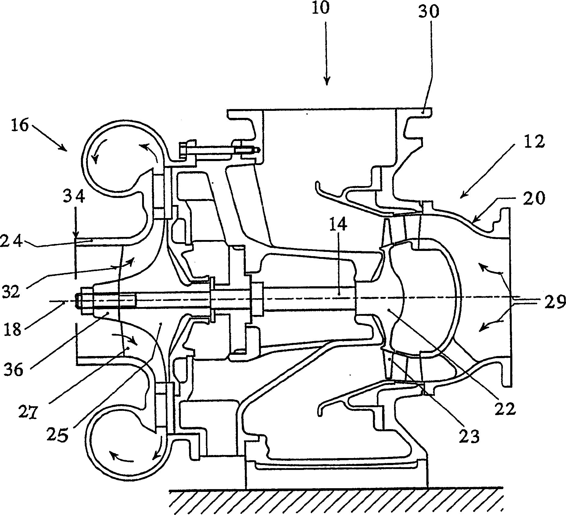
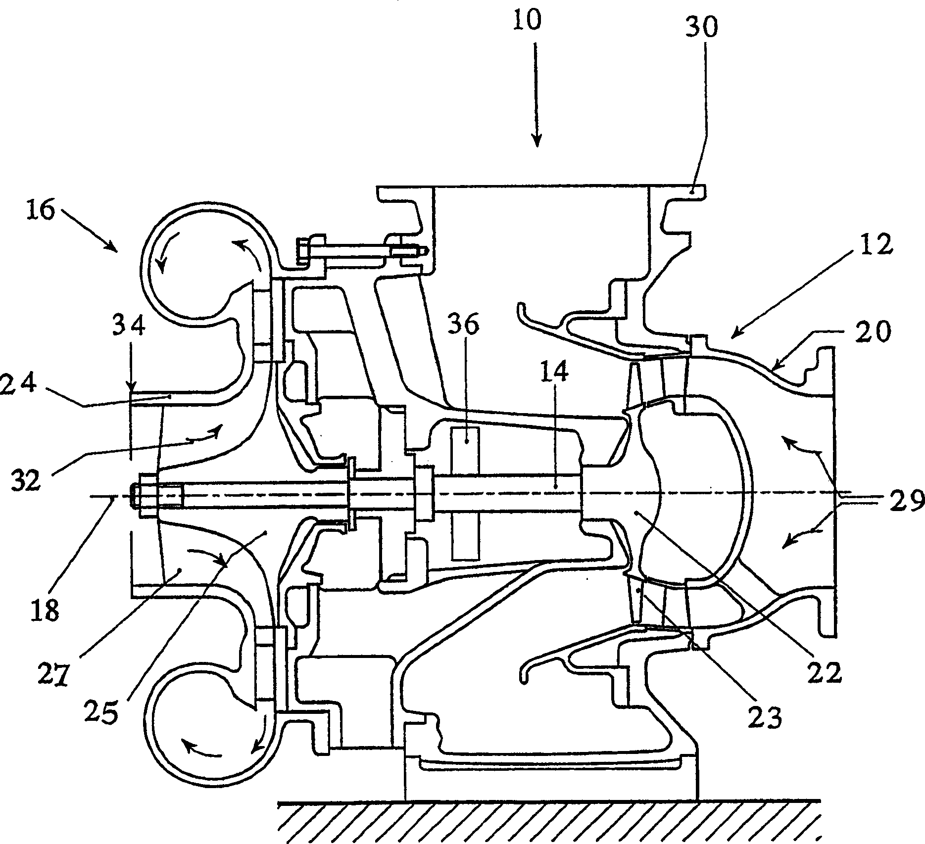
[0022] figure 1 and 2 Each shows a cross-sectional view of a turbocharger 10 with a high-speed rotating electric machine unit 11 along their longitudinal axis 18 . Each high speed rotating electric machine unit 11 comprises a turbine 12 and a compressor 16 which are connected to each other by a common turbocharger shaft 14 . The turbine 12 has a turbine wheel 22 surrounding a turbine housing 20 with turbine blades 23 . The compressor wheel 26 has compressor blades 27 which are regularly distributed around the compressor hub 25 . A compressor wheel 26 peripherally surrounds the compressor casing 24 and is driven by the turbine 12 by means of the common shaft 14 . The common turbocharger shaft 14 is supported between a compressor wheel 26 and the turbine wheel 22 in a bearing bracket 28 .

[0023] The turbine mount 20 forms a flow duct 29 which is connected to the exhaust pipe of the internal combustion engine (not shown). The air flow duct 29 leads through the turbine 22 ,...


PUM


Abstract

The turbocharger has a high-speed rotor unit with turbocharger shaft (14), turbine rotor (22), and compressor rotor. A torsion oscillation damper (36) is located on the shaft to dampen shaft oscillations generated by higher engine operation. The damper is e.g. a viscose torsional vibration damper, oil displacement damper, rubber damper, or silicone oil damper. The damper is fastened to the turbocharger shaft in the area of the compressor, and esp. on the inlet side in front of a compressor hub (25) of the compressor rotor.

Description

technical field [0001] The invention relates to a turbocharger according to the features stated in the preamble of claim 1 . Background technique [0002] Turbochargers are used to increase the power of reciprocating piston engines. They have a high-speed rotating electrical unit consisting of a turbine, a compressor and a shaft coupling the turbine and compressor. In an exhaust gas turbocharger, the turbocharger's turbine runs on the exhaust gas of the internal combustion engine. The turbines rely on a common shaft to drive the compressors. Gas compressed by the compressor is supplied to the combustion chambers of the engine, where it is used to charge the engine. The exhaust gas pressure from the internal combustion engine acting on the turbine is not constant. This may excite vibrations of the turbocharger shaft. The pressure fluctuations are related in particular to the switching behavior of the engine exhaust valves and the construction of the exhaust pipe. The ma...

Claims


Application Information

Patent Timeline
Patent Type & Authority Applications(China)
IPC IPC(8): F02B39/00F01D5/02F01D25/00F01D25/04F02C1/00F02C6/12F04D25/04F04D29/66F16F15/10F16F15/16
CPCF02C6/12F04D29/668F05D2220/40F04D25/04F05B2260/96F05D2260/96F01D25/04F05B2220/40Y02T10/144F01D5/027
Inventor M·罗斯
Owner ABB TURBO SYST
Features
  • R&D
  • Intellectual Property
  • Life Sciences
  • Materials
  • Tech Scout
  • Unparalleled Data Quality
  • Higher Quality Content
  • 60% Fewer Hallucinations
Learn More