

Fiber clock deep filter for reclaiming sewage
A technology of depth filter and fiber reuse, applied in distributor, choke ring and fiber cloth filter material, sieve plate, screw propeller field, can solve the problems of weakening strength and hot water resistance, and reduce investment cost and operating costs, improving filtration accuracy, and improving economic efficiency.
Inactive Publication Date: 2004-12-29
程中和
View PDF2 Cites 13 Cited by
- Summary
- Abstract
- Description
- Claims
- Application Information
AI Technical Summary
Problems solved by technology
If the design of our filter material is unreasonable, the fiber will be artificially thinned in the process of making the filter material, which will greatly weaken its strength and hot water resistance
Method used
View moreImage
Smart ImageViewing Examples

Examples
Embodiment Construction
[0045] Below in conjunction with accompanying drawing and embodiment describe in detail:
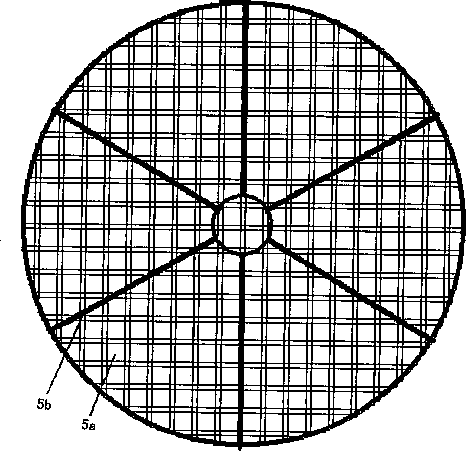
[0046] Depend on figure 2 It can be seen that the sieve plate 5 is composed of square sieve holes 5a and ribbed plates 5b; 3-6 ribbed plates 5b are equiangularly distributed on the square sieve holes 5a. The square sieve hole 5a is a uniquely designed square sieve hole without cutting process.
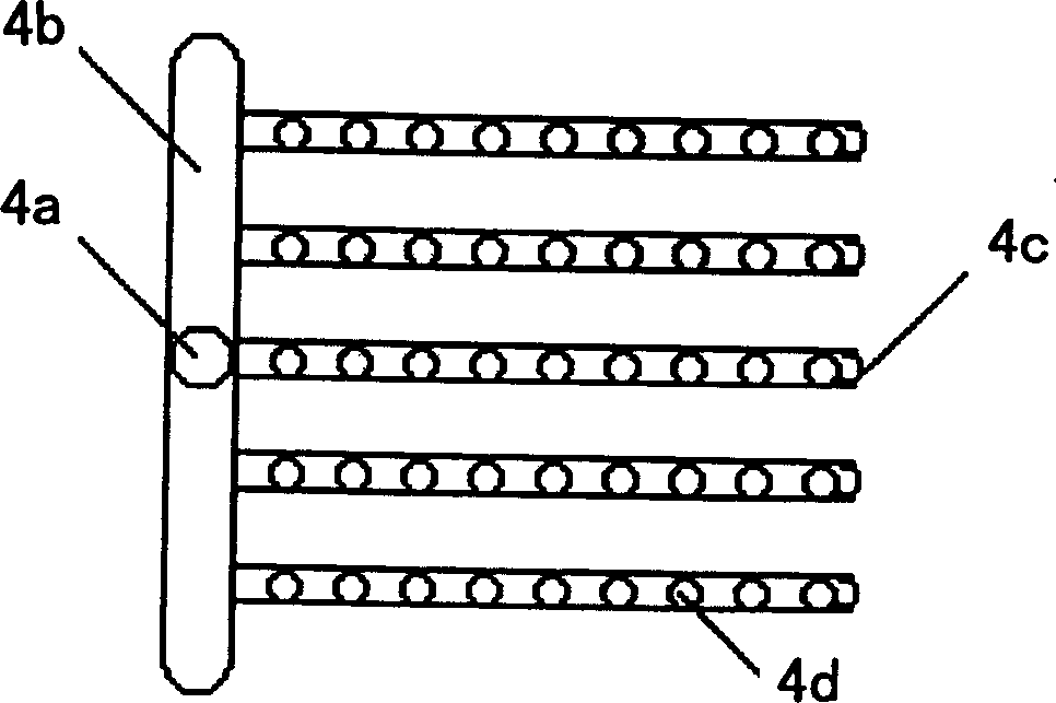
[0047] Depend on image 3 It can be seen that the distributor 4 is composed of a main water inlet pipe 4a, a water inlet pipe 4b, and a liquid distribution pipe 4c, which are connected in sequence; there is a small hole 4d on the liquid distribution pipe 4c.
Login to View More PUM
 Abstract
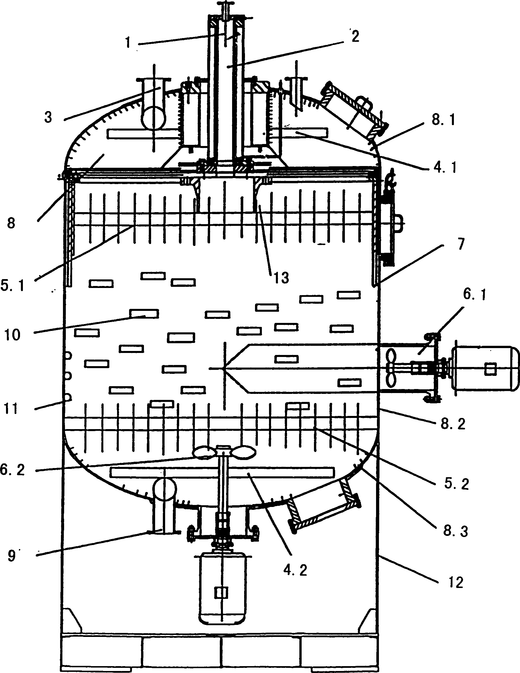
The present invention is one sewage reusing fiber fabric filter as one oil bearing sewage processing apparatus, and is developed on the basis of single stage efficient fiber fabric filter. The sewage reusing fiber fabric filter has increased upper planar sieve plate, lower planar sieve plate, side spiral propeller, lower spiral propeller, upper distributor, lower distributor and choking ring, and has no conic sieve plate, high pressure water nozzle and stirring sieve plate. The choking ring makes the side flow forming whirl flow raising filtering precision; the lower spiral propeller loosens the compressed filtering material under the hydraulic action; and the side spiral propeller rotates the loosened filtering material to reach the aim of back washing. The present invention has high filtering precision, high yield and low cost and may industrially applied.
Description
technical field [0001] The invention relates to oily sewage treatment equipment; in particular, it relates to a sieve plate, a screw propeller, a distributor, a choke ring and a fiber cloth filter material. Background technique [0002] The extraction of oil requires filling the oil well with a large amount of water to suspend the oil and extract it. The follow-up work, that is, the treatment of oily sewage in oil fields, is another voluminous project. [0003] At present, the treatment of oily sewage in oil fields is generally multi-stage treatment, including primary treatment and advanced treatment. [0004] The main problem of the fiber ball filter is that the side flow, partial flow, laminar flow, and crevice flow of the fiber ball have not been solved well, so that the oily sewage flows directly from these places. The biggest shortcoming of the fiber ball is that it is affected by the incoming water. If the incoming water fluctuates slightly, the fiber filaments of th...
Claims
Login to View More Application Information
Patent Timeline
 IPC IPC(8): B01D24/14C02F1/40
Inventor程中和
Owner程中和