
Elastic floating body and manufacturing method thereof

A floating body and elastic technology, applied in the direction of non-magnetic metal hulls, buoys, hulls, etc., can solve the problems of high follow-up cost, long maintenance-free time, low maintenance cost, etc., achieve excellent physical properties and processing performance, and long maintenance-free time , low maintenance costs

Active Publication Date: 2004-12-29
ZHUHAI TIANYUE TECH
View PDF2 Cites 12 Cited by
  • Summary
  • Abstract
  • Description
  • Claims
  • Application Information

AI Technical Summary

Problems solved by technology

[0004] 1. Due to the high strength and hardness of the steel floating body, ships colliding with it, especially small ships, will cause greater damage;
[0005] 2. Due to the poor impact resistance of steel buoys, large ships colliding with them will damage them and cause the buoys to sink after entering the water. The sunken buoys will pose a threat to the navigation of ships;
[0006] 3. Due to the weight of the steel buoy, it is difficult to transport, release and recycle the buoy;
[0007] 4. Since the steel floating body is easy to corrode, the maintenance workload such as rust removal, removal of marine deposits, painting, etc. is heavy and the follow-up cost is high
[0009] FRP floating body has the advantages of corrosion resistance, easy coloring and light weight, but the surface of FRP floating body is fragile, its impact resistance is very poor, and its performance of aging resistance and temperature change resistance is also poor.
[0010] Chinese Patent Publication No. CN1046711, published on November 7, 1990, discloses a plastic buoy named "All-plastic navigation buoy". Its floating body has the advantages of corrosion resistance, easy coloring and light weight, but the surface of the plastic floating body is relatively Fragile, its impact resistance is poor, and its performance of aging resistance and temperature change resistance is also poor
[0011] The Chinese Patent Publication No. is CN2414000, and the publication date was January 10, 2001, disclosing a rubber buoy named "The Buoyant Drum Used in Water Navigation Mark Setting", the buoy has the advantages of impact resistance and corrosion resistance, However, the rubber floating body is not easy to color, and it is difficult to form and process
[0012] Moreover, the floating bodies of the above-mentioned FRP buoys, plastic buoys and rubber buoys are filled with foam materials in the shells made of glass fiber reinforced plastics, plastics or rubber. The water absorption rate of the filler is high, so that the floating body has the disadvantages of large buoyancy loss and poor physical properties that are difficult to overcome
[0013] However, the fenders in the prior art are mostly made of rubber or inflatable rubber, which has the disadvantages of being difficult to color and difficult to form and process.
[0014] Therefore, there is no floating body in the prior art that has the advantages of impact resistance, corrosion resistance, easy processing, long maintenance-free time, low maintenance cost, and long life.

Method used


Image

  • Elastic floating body and manufacturing method thereof
  • Elastic floating body and manufacturing method thereof
  • Elastic floating body and manufacturing method thereof

Examples


Embodiment 1

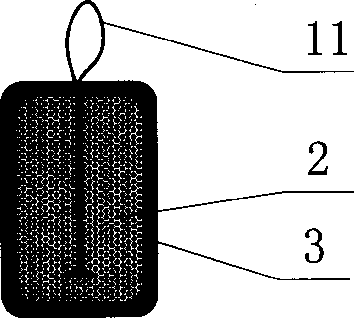
[0035] Such as figure 1 As shown, the present invention includes a floating body 1 which is composed of an elastic foam inner core 2 and an elastic armor 3 covering the surface of the elastic foam inner core 2. The elastic foam inner core 2 is made of a polymer foam material. The polymer material can be plastic or a mixture of plastic and rubber or polyurethane. The present invention uses one of plastics—EVA resin; the elastic armor 3 It is made of polyurethane or polyurea or a mixture of polyurethane and polyurea. The present invention uses a mixture of polyurethane and polyurea.

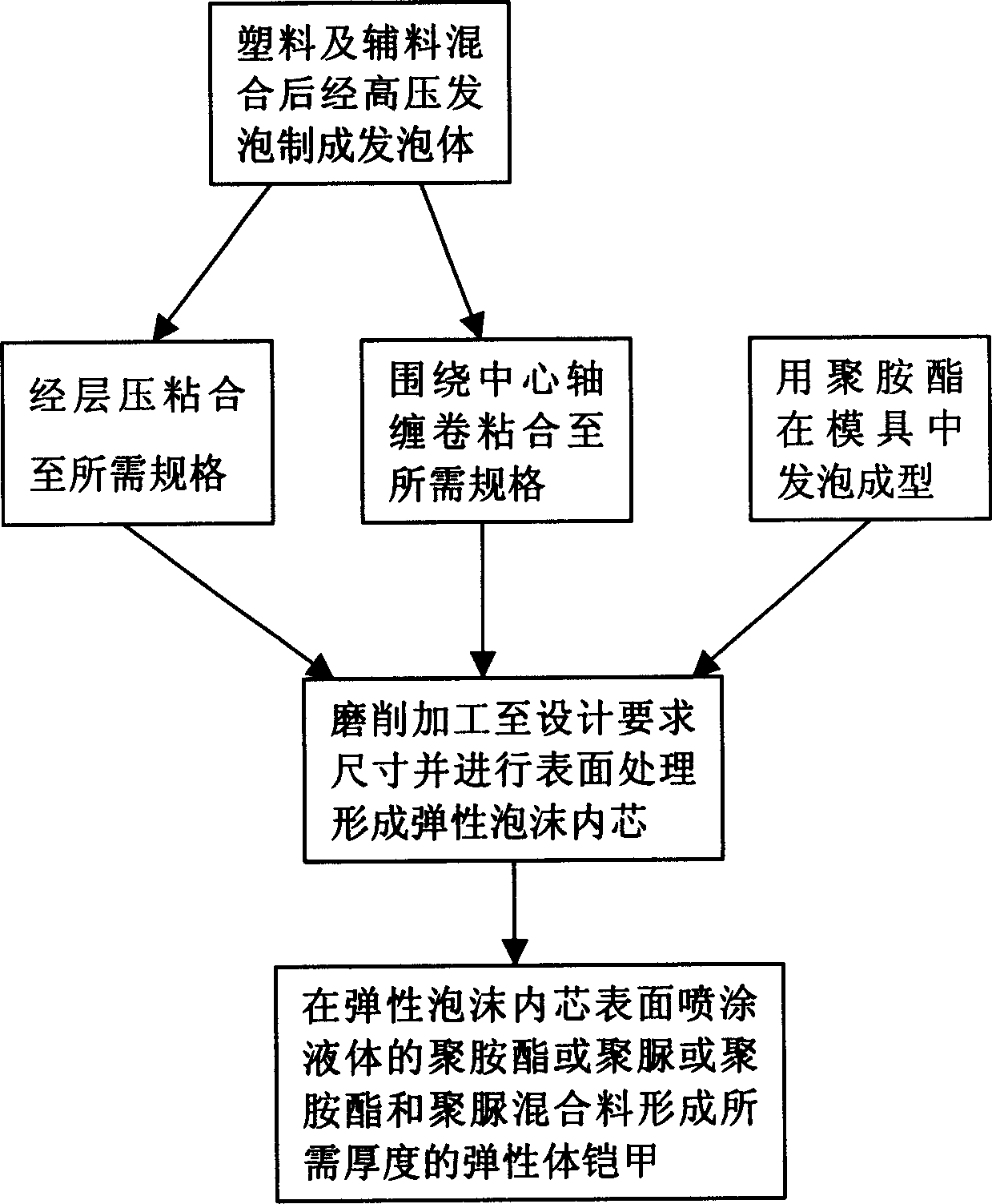
[0036] Such as figure 2 As shown, the manufacturing process steps of the present invention are as follows:

[0037] 1. First, make the elastic foam inner core 2.

[0038] 1. The inner core can be made of plastic foam inner core or polyurethane foam inner core.

[0039] 1) The production methods of plastic foam include molding method and extrusion method:

[0040] I. The molding method is to put plast...

Embodiment 2

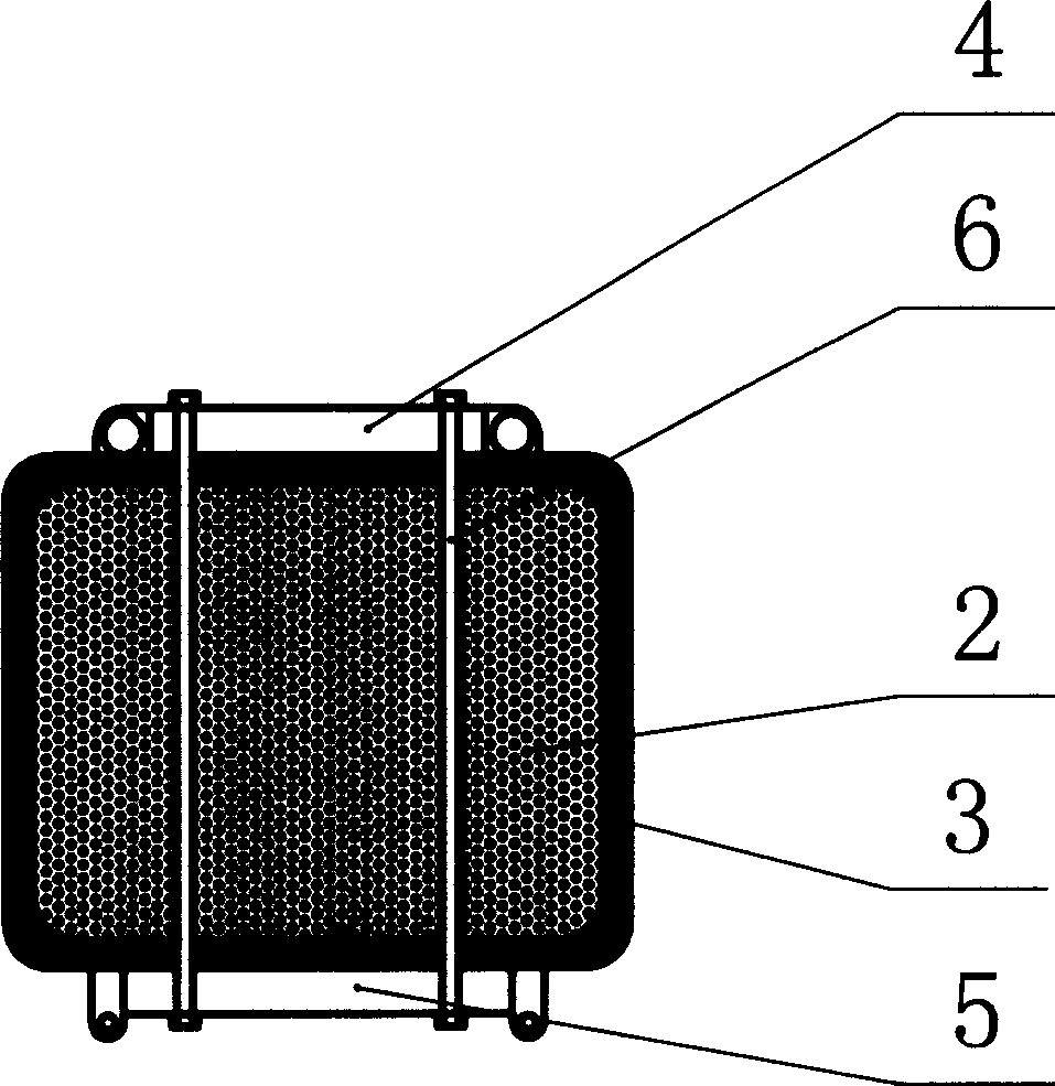
[0052] Such as image 3 As shown, for a slightly larger-sized elastic floating body, the present invention also includes an upper cover plate 4, a lower support plate 5, and four connecting rods 6.

[0053] During production, before spraying the elastic armor 3, drill 4 through holes on the molded elastic foam inner core 2 along a circle with the inner core center as the axis to install the connecting rod 6; set the upper part of the molded floating body 1 The upper cover 4 and the lower support plate 5 are provided, and the upper cover 4, the lower support plate 5 and the floating body 1 are connected as a whole by the connecting rod 6.

[0054] The other features are the same as the first embodiment.

Embodiment 3

[0056] Such as Figure 4 As shown, for an elastic floating body with a larger specification, the present invention also includes an upper cover plate 4, a lower support plate 5, and a center tube 7.

[0057] During production, before spraying the elastic armor 3, drill a through hole in the center of the formed elastic foam core 2 and install the center tube 7; The tube 7 is tightly connected, and the upper cover 4, the lower support plate 5 and the floating body 1 are connected as a whole through the central tube 7.

[0058] The other features are the same as the first embodiment.


PUM


Abstract

The present invention discloses one kind of elastic float, and aims at providing one kind of elastic float with high shock strength, high corrosion resistance, easy manufacture, no maintenance, long service life and other advantages and its making process. The elastic float includes float body comprise elastic foamed core and elastic shield. The elastic float is made through making elastic core with foamed polymer material and spraying with high pressure spraying gun the polyurethane, polyurea or their mixture onto the surface of the elastic core to form shield, without interval between the elastic foamed core and the elastic shield. The present invention may be used as ship fender and floating buoy.

Description

Technical field [0001] The invention relates to an elastic floating body and a manufacturing method thereof. Background technique [0002] Navigation marks and fenders are important facilities to ensure the safe navigation and berthing of ships. [0003] For a long time, the navigation mark on the water is mainly made of steel floating bodies, but with the development of economy, the density of ships on the channel has increased, making the steel floating bodies show the following shortcomings: [0004] 1. Due to the high strength and hardness of the steel floating body, ships colliding with it, especially small ships, will cause greater damage; [0005] 2. Due to the poor impact resistance of the steel floating body, large ships colliding with it will cause damage to the floating body and sinking after flooding, and the sunken buoy will pose a threat to the ship's navigation; [0006] 3. Due to the weight of the steel float, it is difficult to transpor...

Claims


Application Information

Patent Timeline
Patent Type & Authority Applications(China)
IPC IPC(8): B63B5/24B63B22/00
Inventor 宋学刚
Owner ZHUHAI TIANYUE TECH
Learn More