Plane location method for whole knee-joint replacement by robot

A technology of total knee replacement and plane positioning, which is applied in the field of advanced manufacturing and automation, can solve the problems of a large amount of computer running time, increase the operation cost, and high complexity, and achieve the effect of avoiding errors, simple method, and easy implementation

Inactive Publication Date: 2005-01-05
SHANGHAI JIAO TONG UNIV
View PDF0 Cites 3 Cited by
  • Summary
  • Abstract
  • Description
  • Claims
  • Application Information

AI Technical Summary

Problems solved by technology

The disadvantages of this type of positioning method are: one more positioning operation for implanting titanium nails is required, which makes the patient suffer more; CT scanning greatly increases the operation cost, and the 3D reconstruction step requires a lot of computer running time; once the femur position changes, Re-matching algorithms with high complexity need to be run
In the positioning process, a large number of traditional methods are point positioning, that is, the probe directly points to a certain point on the tool or femur to obtain the three-dimensional coordinates of the point, but in the actual environment, a large number of objects are The plane of the plane, using the traditional probe to point measurement method to obtain the plane will produce a large error

Method used


Image

  • Plane location method for whole knee-joint replacement by robot
  • Plane location method for whole knee-joint replacement by robot
  • Plane location method for whole knee-joint replacement by robot

Examples


Embodiment Construction

[0021] In order to better understand the technical solutions of the present invention, a further detailed description will be made below in conjunction with the accompanying drawings and embodiments.

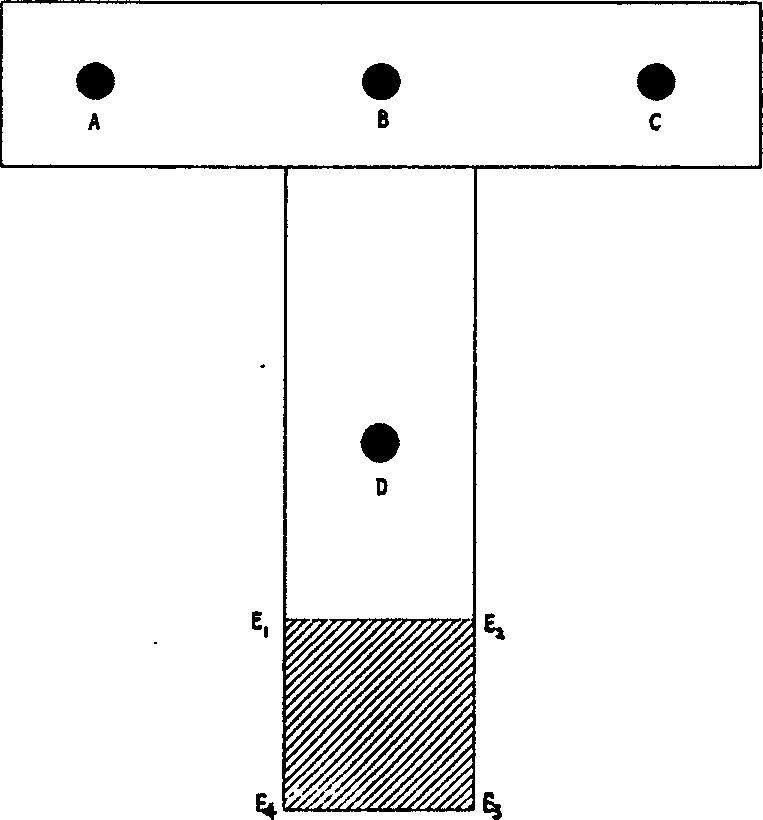
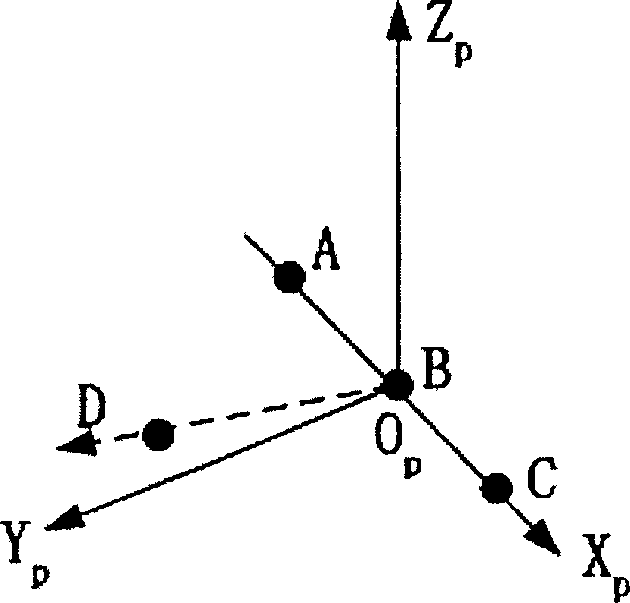
[0022] Figure 1 is The probe designed for the positioning plane of the present invention, A, B, C, D are mark points composed of four infrared light-emitting diodes, E 1 E. 2 E. 3 E. 4 As the positioning plane on the probe, A, B, and C should be on the same straight line as much as possible, and BD should be perpendicular to the straight line formed by ABC as much as possible. definition is the X-axis, since the three points B, C, and D are coplanar, then define is the Y axis, then X×Y is the Z axis, and B is the origin (such as figure 2 ).

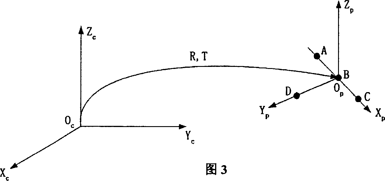
[0023] FIG. 3 is a schematic diagram of the relationship between the probe coordinate system and the camera coordinate system. Let the coordinates of point A in the camera be (X A c , Y A c ,Z A c ), where the superscript ...


PUM


Abstract

A plane locating method for the whoel knee joint displacing operation performed by robot includes such steps as constituting the locating probe with 4 infrared LEDs and locating pane, creating its coordinate system, finding out the relation between the coordinate systems of probe and camera, aligning the locating plane of probe with any plane, sliding several times, finding out the equation of said locating planein the coordinate of camera, scaling probe, finding out the equation of locating plane in the coordinate system of probe, and using the scaled probe to locate the plane on object.

Description

technical field [0001] The invention relates to a plane positioning method in robotic total knee replacement surgery, which is used for robot total knee replacement surgery without CT. It belongs to the field of advanced manufacturing and automation (medicine). Background technique [0002] In our country, thousands of patients with severe arthritis need total knee replacement every year. Artificial knee replacement is a typical orthopedic prosthesis implantation operation. The key operations are five directional cuts to the patient's femur and longitudinal opening of the tibia. The placement position of the prosthesis, the accuracy of cutting and opening are all directly related to the quality of the operation. In addition, the position and direction of the cutting tool in the operation also directly determine the accuracy of the operation. Among all these factors, the object plane plays a crucial role. The positioning of the object plane determines the coordinate posit...

Claims


Application Information

Patent Timeline
Patent Type & Authority Applications(China)
IPC IPC(8): A61B90/10
Inventor 刘宏建罗毅刘允才
Owner SHANGHAI JIAO TONG UNIV
Why Eureka
Try Eureka