Group battery composed of single air chamber solid oxide fuel cell

A solid oxide and fuel cell technology, applied in the direction of solid electrolyte fuel cells, fuel cell grouping, etc., can solve the problems of increasing the volume and weight of the battery pack, reducing the power density, and unfavorable rapid start of the battery pack

Inactive Publication Date: 2005-01-12
HARBIN INST OF TECH
View PDF0 Cites 11 Cited by
  • Summary
  • Abstract
  • Description
  • Claims
  • Application Information

AI Technical Summary

Problems solved by technology

On the other hand, since a battery pack formed by connecting N cells in series must be divided into 2N gas chambers, which must be fed with their own gas, so the system structure becomes very complicated, difficult to manufacture, and after a local failure, maintenance very difficult
For single-chamber SOFC, it has been reported (US patent) to form a plurality of alternately arranged anodes and cathodes on one side of an electrolyte sheet, separated by trenches, to form multiple single cells, and then

Method used


Image

  • Group battery composed of single air chamber solid oxide fuel cell
  • Group battery composed of single air chamber solid oxide fuel cell

Examples


specific Embodiment approach 1

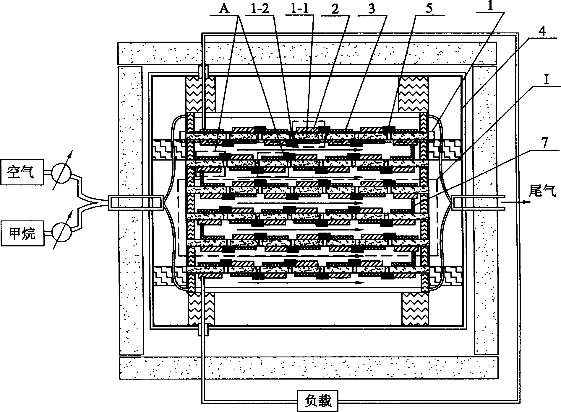
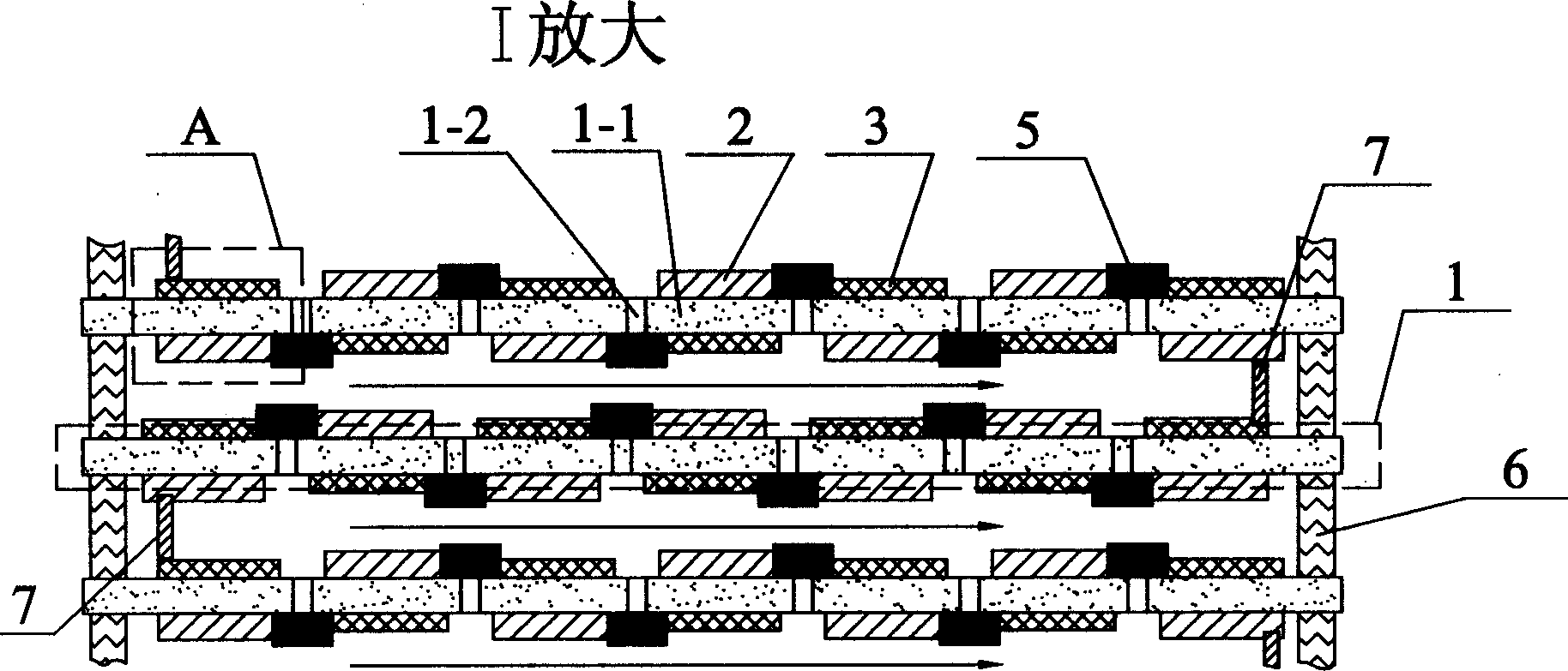
[0005] Specific Embodiment 1: This embodiment includes a group of electrolyte sheets 1 arranged in a container 4, and the two sides of each electrolyte sheet 1 are alternately provided with anodes 2 and cathodes 3, and the polarity of the electrodes on both sides of the same position of the electrolyte sheet 1 On the contrary, a single cell A is formed, and an electrolyte isolation area 1-2 is provided between the electrolytes 1-1 of two adjacent single cells A, and the cathode of the single cell and the anode of the next single cell are connected in series through a conductor, All the electrolyte sheets 1 in the container 4 are connected through wires 7 so that all the single cells A in the container 4 are connected in series, and all the single cells connected in series become a series battery pack.

specific Embodiment approach 2

[0006] Embodiment 2: In this embodiment, each group of electrolyte sheets 1 is arranged parallel to each other. This parallelism does not emphasize absolute parallelism. It only needs to not intersect with each other. It can be parallel to the same direction as the gas flow direction, or It can be parallel to the direction perpendicular to the direction of gas flow, ceramic fibers are set between two adjacent electrolyte sheets 1 as the support body 6, and the connection is realized with high-temperature wires 7, so that a transverse direction can be formed between adjacent electrolyte sheets 1. The flowing gas conveying channel is used to convey the fuel and oxygen mixed reaction gas and tail gas.

specific Embodiment approach 3

[0007] Specific embodiment three: In this embodiment, anodes 2 and cathodes 3 are alternately arranged on both sides of each electrolyte sheet 1, and the raw materials of the anode are transition metal Ni and lanthanide rare earth oxide CeO 2 mixture, the raw material of the cathode is the rare earth transition group composite oxide La 0.7 Sr 0.3 MnO 3 with transition group oxide MnO 2 The raw material of the electrolyte is an oxide solid solution yttria stabilized zirconia with a cubic fluorite structure, and an electrolyte isolation area 1-2 is provided between the electrolytes 1-1 of two adjacent single cells A, and the electrolyte isolation area 1- The formation method of 2 is as follows: first pre-sinter the molded electrolyte sheet 1 at 900-1200°C for 2-6 hours to form a green body with holes, cover the area that needs to be reserved as an electrode, and then cover the area containing La and / Or the saturated solution of Pb nitrate is injected into the predetermined ...


PUM


Abstract

Anode and cathode is setup at two sides of each electrolyte piece alternately. Opposite polarities at two sides of an electrolyte piece constitutes a single battery. There is an electrolyte-isolated region between two adjacent single batteries. Cathode of single battery is connected to anode of adjacent battery through wire; thus, all single battery in a container is cascaded. Comparing with present dual air chamber battery group, the invention lowers requirement for material and fabricating technique, and reduces size weight.

Description

technical field [0001] The invention relates to a solid oxide fuel cell stack. Background technique [0002] Solid oxide fuel cell (SOFC) has the advantages of high efficiency, low pollution and wide range of fuel sources, and is one of the most potential power generation technologies in the 21st century. A single SOFC (single cell) is mainly composed of electrolyte, cathode and anode. Due to the low output voltage and small output current of a single cell, it cannot meet the actual needs of most electrical appliances, so it is necessary to combine multiple single cells in series and parallel. up, forming a battery pack. The composition of SOFC battery packs can not only be connected with wires in the external circuit like ordinary batteries, but also can be directly connected through a certain design, that is, SOFC stacking. This stacking connection usually requires the use of connecting materials ( bipolar plates). SOFC can use a variety of fuels such as hydrogen, coal ...

Claims


Application Information

Patent Timeline
IPC IPC(8): H01M8/10H01M8/24
CPCY02E60/521Y02E60/50
Inventor 吕喆苏文辉刘江黄喜强刘志国苗继鹏李长玉
Owner HARBIN INST OF TECH
Why Eureka
Try Eureka