Plastic profiled screw-thread interface thin-walled stainless steel pipes and sealing method of same
A threaded interface and plastic forming technology, which is applied in threaded connections, pipes/pipe joints/fittings, passing components, etc., can solve problems such as unsuitable for thin walls and damaged pipe walls, and achieve increased rigidity and strength, increased rigidity, The effect of high production efficiency
- Summary
- Abstract
- Description
- Claims
- Application Information
AI Technical Summary
Problems solved by technology
Method used
Image

Examples
Embodiment 1
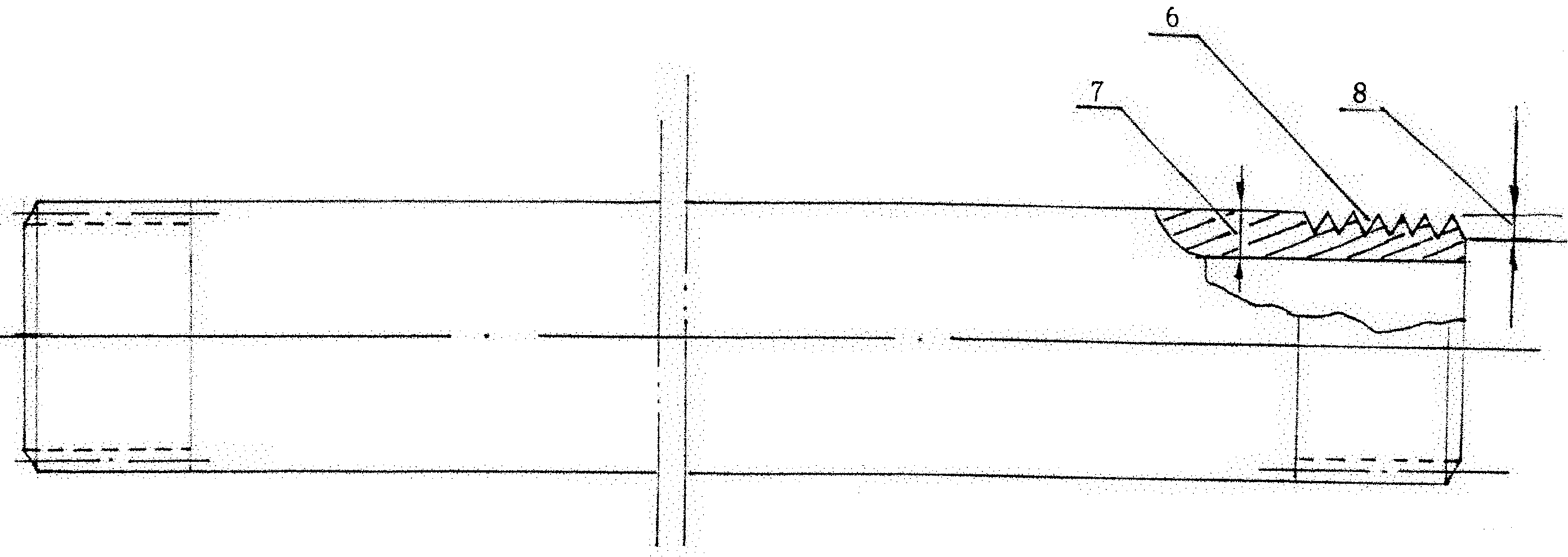
[0024] A. Forming of external thread interface 2 (see Image 6 )
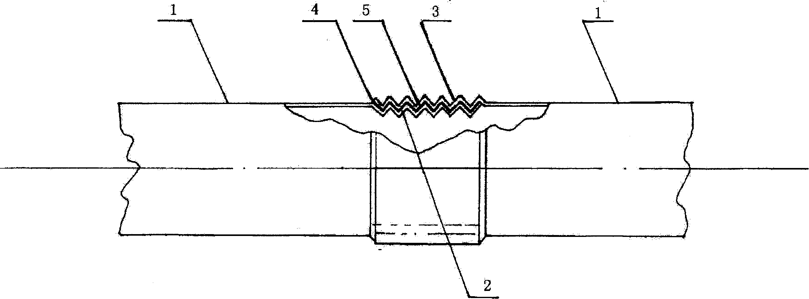
[0025] Insert the end of the pipe 1 into the inner hole of the outer mold 20 with threads on the inner surface, insert the rubber mold 21 and the shaft column 22 into the inner hole of the pipe 1, and apply an axial force 31 to the shaft column 22, so that the rubber mold 21 After being compressed by the axial force 31 , a radial bulging force is generated, forcing the pipe wall at the end of the pipe 1 to undergo plastic deformation according to the threads of the outer mold 20 to become the externally threaded interface 2 . Disassemble the outer mold 20, take out the rubber mold 21 and the shaft column 22, and complete the processing of the external thread interface 2.
[0026] B, forming of internal thread interface 3 (see Image 6 )
[0027] Insert the end of the pipe 1 into the inner hole of the outer mold 20 (the inner diameter of the outer mold 20 for processing the internal thread interface 3 is two ...
Embodiment 2
[0030] A. Forming of external thread interface 2 (see Figure 7 )
[0031] Insert the inner mold 23 with threads on the outer surface into the inner hole of the end of the pipe 1, put the rubber mold 24, the pressure sleeve 25 and the outer ring 26 on the outer circle of the pipe 1 respectively, and apply an axial force 31 to the pressure sleeve 25 , so that the rubber mold 24 is compressed by the axial force 31 to produce a radial shrinkage force, forcing the pipe wall at the end of the pipe 1 to undergo plastic deformation according to the thread of the inner sleeve mold 23 to become the external thread interface 2, and pull out the pipe 1, and remove the inner mold 23 to complete the processing of the external thread interface 2.
[0032] B, forming of internal thread interface 3 (see Figure 7 )
[0033] Insert the inner cover mold 23 (the inner cover mold 23 for processing the internal thread interface 3 than the outer diameter of the inner cover mold for processing th...
Embodiment 3
[0036] A. Forming of external thread interface 2 (see Figure 8 )
[0037] Insert the mandrel 30 into the inner hole at the end of the pipe 1 to form a whole, and send it to the right between the rolling wheels 27, 28, 29, so that the pipe 1 and the rolling wheels 27, 28, 29 are aligned according to their respective axes. Rotate at a linear speed, and make the gap between the threads on the surface of the rolling wheels 27, 28, 29 and the thread bite points of the mandrel 30 equal to the wall thickness of the threaded pipe end to be processed, and the pipe wall is formed under the rolling of the rolling wheel threads Plastic deformation, and molding according to the surface thread shape of the mandrel 30, exit the processed external thread interface 2.
[0038] B, forming of internal thread interface 3 (see Figure 8 )
[0039] Insert the mandrel 30 (the outer diameter of the mandrel 30 for processing the internal thread interface 3 is two pipe wall thicknesses larger than ...
PUM
 Abstract
Description
Claims
Application Information
 - R&D
- Intellectual Property
- Life Sciences
- Materials
- Tech Scout
- Unparalleled Data Quality
- Higher Quality Content
- 60% Fewer Hallucinations
Browse by: Latest US Patents, China's latest patents, Technical Efficacy Thesaurus, Application Domain, Technology Topic, Popular Technical Reports.
© 2025 PatSnap. All rights reserved.Legal|Privacy policy|Modern Slavery Act Transparency Statement|Sitemap|About US| Contact US: help@patsnap.com