

Motor driving apparatus
A driving device and motor technology, applied in the direction of control of electromechanical transmission, motor generator control, AC motor control, etc., can solve the problems of no contribution, low efficiency, decreased efficiency, etc., and achieve the effect of further stabilizing the weak magnetic field control
- Summary
- Abstract
- Description
- Claims
- Application Information
AI Technical Summary
Problems solved by technology
Method used
Image

Examples
Embodiment approach 1
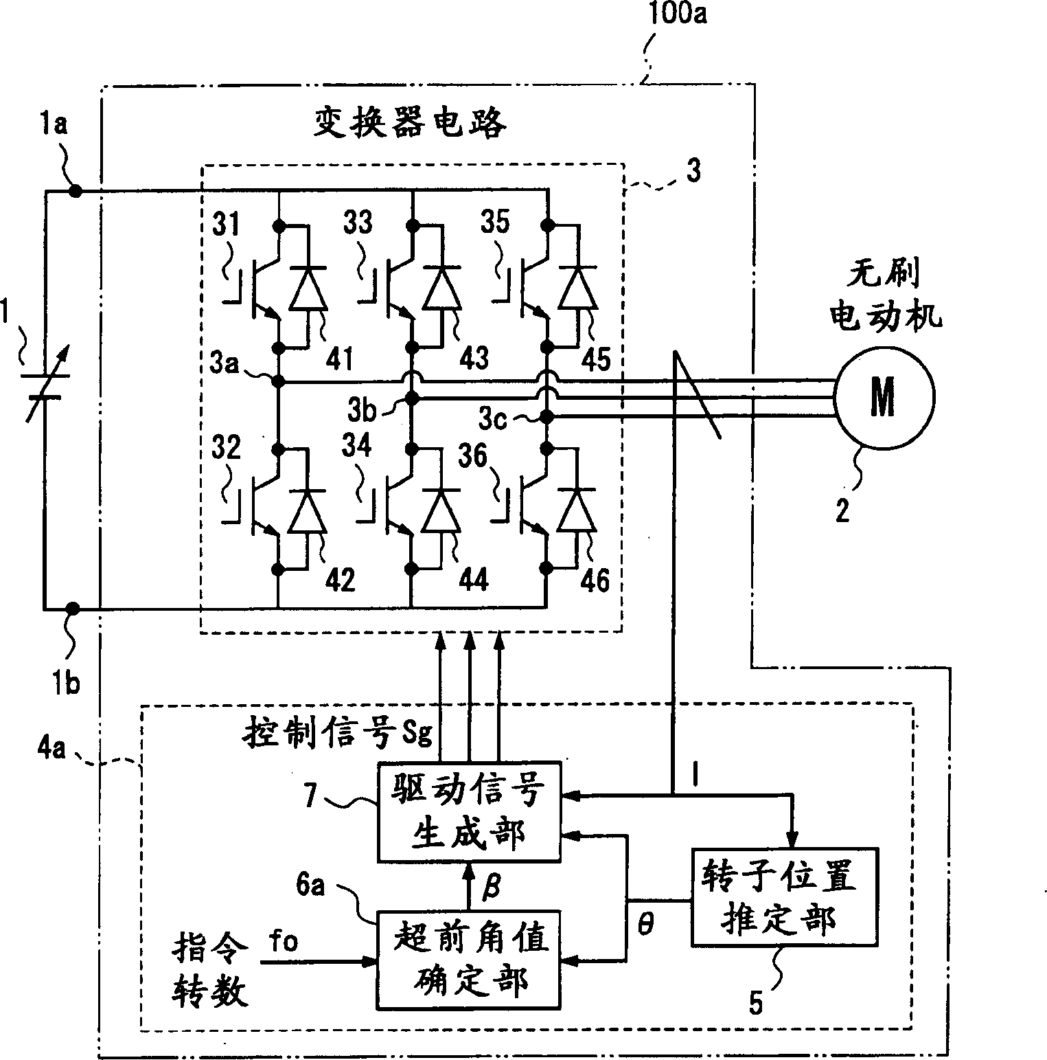
[0105] figure 1 It is a block diagram for explaining the motor drive device according to Embodiment 1 of the present invention.
[0106] The motor driving device 100a of the first embodiment takes the voltage source 1 as an input and drives the brushless motor 2 at any required number of revolutions. A change occurs to perform field weakening control of the brushless motor 2 .
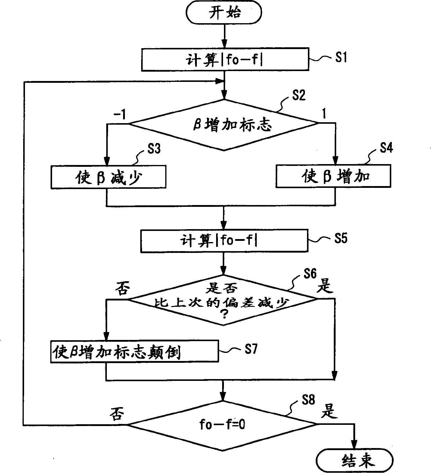
[0107] In Embodiment 1, the motor current lead angle value β is controlled so that the deviation between the commanded rotation speed and the actual rotation speed of the motor becomes zero. In the prior art, the control object in the field weakening control is the field weakening current Id, so in the field weakening control, the lead angle value β of the motor current in Embodiment 1 and the field weakening current shown in the prior art Id is almost the same control object.
[0108] Next, the inverter circuit 3 and the inverter control unit 4a constituting the motor drive device 100a will be desc...
Embodiment approach 2
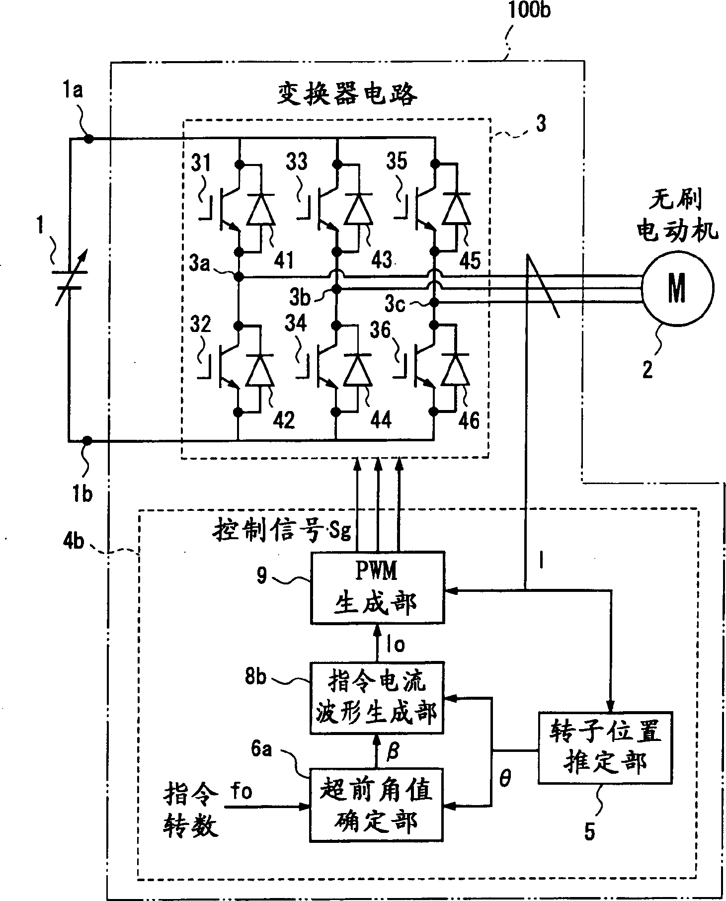
[0144] image 3 It is a block diagram for explaining the motor drive device according to Embodiment 2 of the present invention.
[0145] The motor drive device 100b of the second embodiment is the same as the motor drive device 100a of the first embodiment. The voltage source 1 is used as an input to drive the brushless motor 2 at an arbitrary number of revolutions. By adjusting the lead angle value β of the motor current, the brushless motor 2 Carry out weak magnetic field control. Furthermore, in Embodiment 2, the lead angle value β of the motor current is controlled while maintaining the amplitude value of the current supplied to the motor at a constant value so that o The deviation from the actual number of revolutions f can become zero.
[0146] That is, the motor drive device 100b is composed of an inverter circuit 3 that converts the voltage output from the voltage source 1 into a three-phase AC and outputs it to the motor 2, and an inverter control unit 4b that contr...
Embodiment approach 3
[0163] Figure 5 It is a block diagram for explaining the motor drive device according to Embodiment 3.
[0164] The motor drive device 100c of the third embodiment is the same as the motor drive device 100b of the second embodiment. The voltage source 1 is used as an input to drive the brushless motor 2 at an arbitrary number of rotations. By adjusting the actual number of rotations f of the motor to the maximum The motor current leading angle value β performs field weakening control on the brushless motor 2 .
[0165] That is, the motor drive device 100c is composed of an inverter circuit 3 that converts the output voltage of the voltage source 1 into three-phase alternating current and outputs it to the motor, and an inverter control unit 4c that controls the inverter circuit 3 .
[0166] The inverter control part 4c provides the drive signal Sg to the inverter circuit 3 so that the user can drive the brushless motor 2 with a desired number of revolutions. The command cur...
PUM
 Abstract
Description
Claims
Application Information