Communication system

A technology of communication system and communication method, which is applied in the direction of signal transmission system, transmission system, and near-field transmission system using transceivers, etc., which can solve problems such as the inability to overcome the change of resonance frequency between cards and cards, and achieve the effect of low cost

Inactive Publication Date: 2005-02-02
HITACHI LTD
View PDF0 Cites 64 Cited by
  • Summary
  • Abstract
  • Description
  • Claims
  • Application Information

AI Technical Summary

Problems solved by technology

However, in practice, variations in said measurements due to non-uniform spots are unavoidable
[0012] With regard to the antenna and card storage medium assembly disclosed in cited Patent Document 1 for reading data in a non-contact manner, although the card storag...

Method used


Image

  • Communication system
  • Communication system
  • Communication system

Examples


Embodiment 1

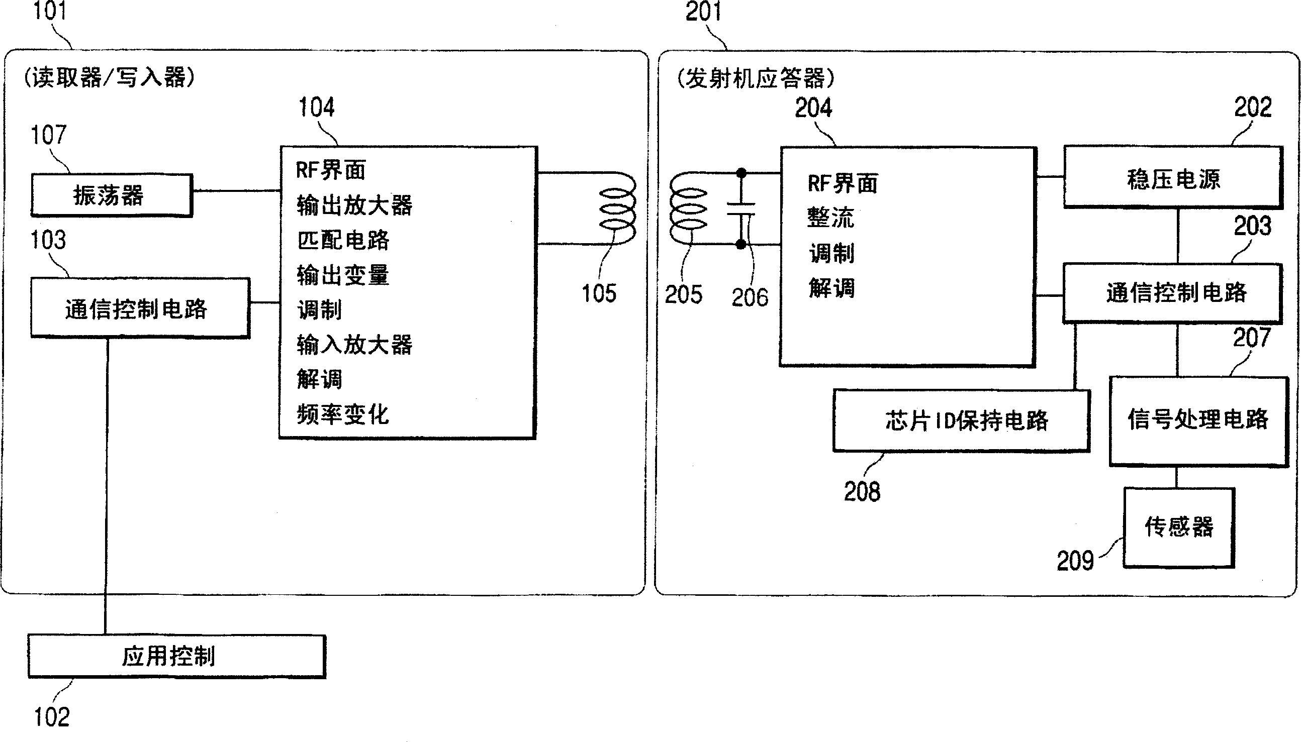
[0035] Attached below figure 1 The preferred embodiment 1 of the present invention is described. figure 1 It is a schematic diagram showing the structure of the electronic circuit module of the reader of the present invention and the chip in the measurement system. The reader 101 includes a radio frequency (RF) interface module (RF control unit, the same below) 104, an oscillator module 107, a communication control circuit module 103, and an outer coil 105. The reader is controlled by the application control module 102. The RF interface module is a circuit module with radio signal transmitting and receiving functions. After the carrier wave generated by the oscillator 107 is modulated by the signal generated by the communication control circuit, it is amplified by the output amplifier according to an output change function and fed back to the outer coil of the reader.

[0036] The chip includes an inner coil 205, a capacitor 206 in a resonance circuit, a radio RF interface 204, ...

Embodiment 2

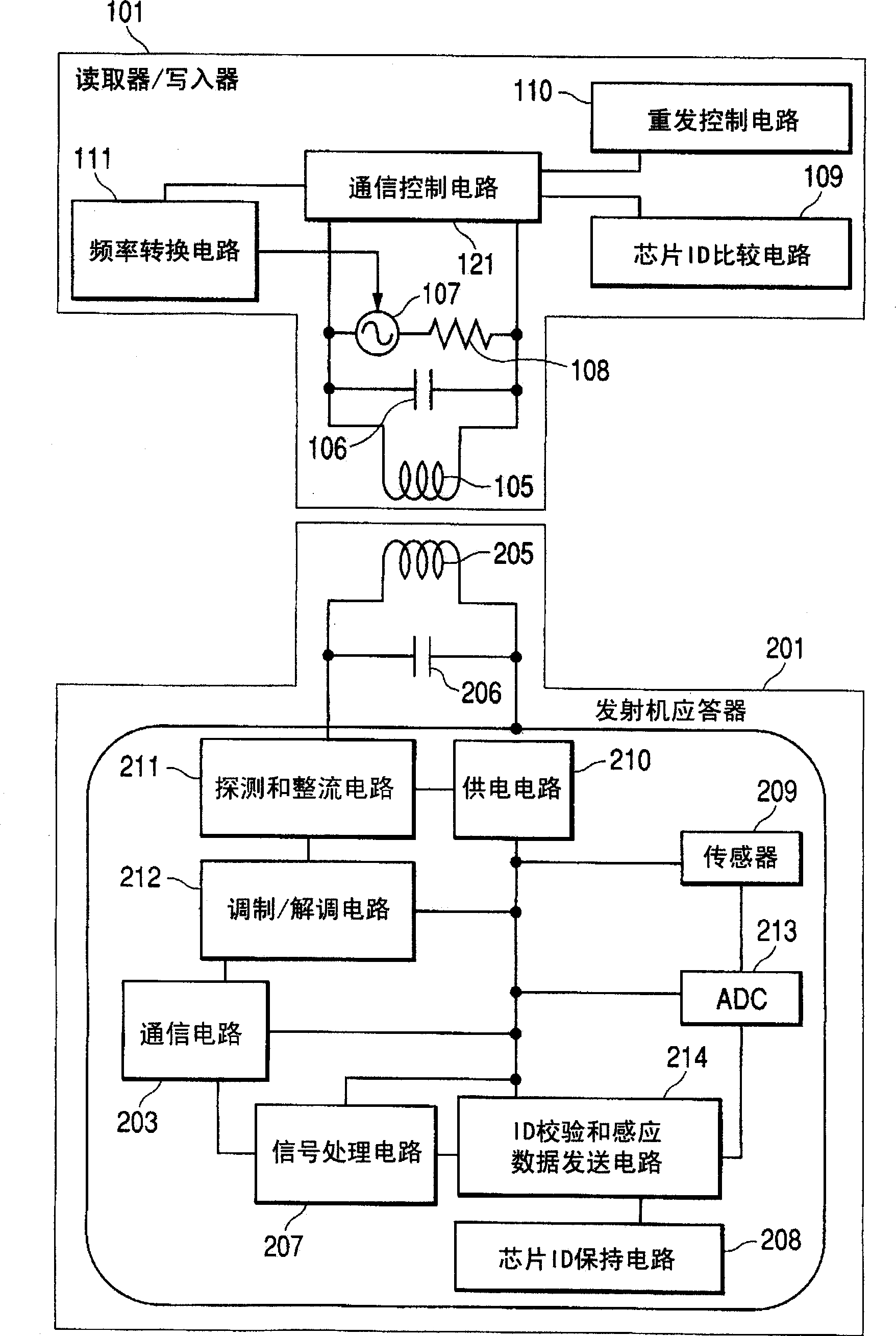
[0042] Combine below figure 2 Another specific embodiment of the present invention is described. figure 2 It is a schematic diagram of the functional modules of the reader and the chip according to the present invention. In the reader, a chip ID comparison circuit 109, a retransmission circuit 110, and a variable frequency oscillator 107 including a series of internal resistors 108 are provided, the oscillation frequency of which can be changed by the frequency conversion circuit 111, and the frequency conversion circuit 111 It operates by controlling the signal sent by the communication control circuit 121, as well as an outer coil 105 and an external resonance capacitor 106 installed in parallel therewith. Inside the chip 201, a circuit including a parallel internal coil 205 and a built-in resonance capacitor 206, a sensor 209, a detection and rectification circuit 211, a modulation / demodulation circuit 212, a communication control circuit 203, and a signal processing circuit 2...

Embodiment 3

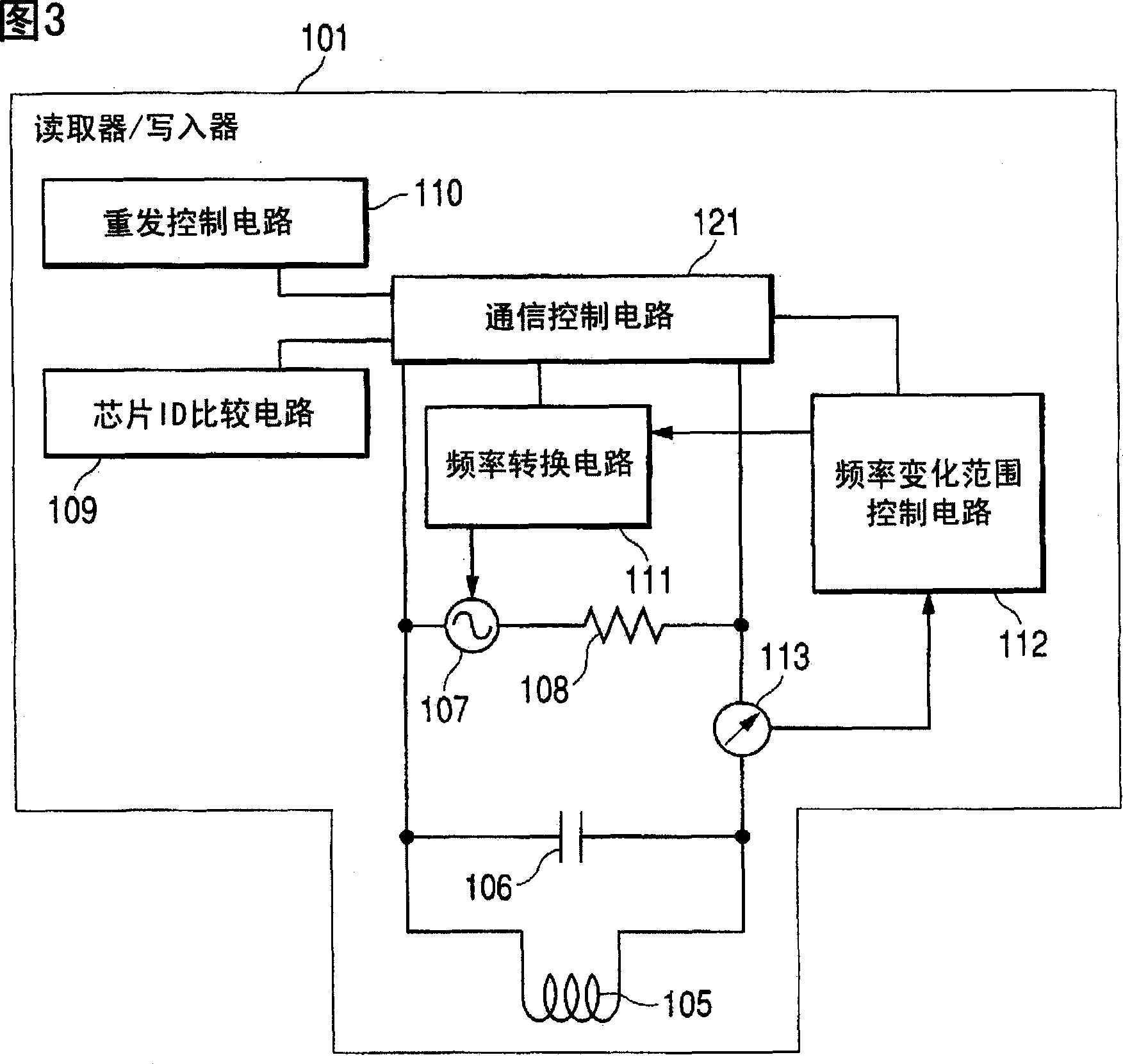
[0044] Next, another preferred embodiment of the present invention will be described with reference to FIG. 3. Fig. 3 is a schematic circuit diagram showing a reader of a measurement system in another embodiment of the present invention. The reader is compatible with figure 2 The reader in Example 2 is different. In addition, a frequency variation range control circuit 112 is connected to the communication control circuit 121, and a current detector 113 is connected in series on one of the lines connecting the parallel circuit and the series circuit in parallel, and the parallel circuit is composed of an inner coil. 105 and an internal resonance capacitor 106, and the series circuit is composed of a variable frequency oscillator 107 and an internal resistor 108. Using a signal detected by the current detector as an input control signal, the frequency variation range control circuit generates a control signal to dynamically change the frequency variation range, and provides the si...


PUM


Abstract

A communication system is provided which enhances communication stability, using chips on which function blocks are formed including sensor, chip ID, and radio transmission/reception functions. The sensor detects biological and chemical materials and physical and stoichiometric quantities such as temperature, pressure, and pH and the sensed results are transmitted to a reader by a radio frequency (RF) function. The chip with the sensor functions at a resonance frequency which is detected by the reader initially during a frequency sweep. No dedicated power source is essential to operate the chips, but instead the chips are triggered into transmitting by the radio frequency signals transmitted from the reader. The frequency and output of transmission from the reader to the chips are variable. Stable communication can be performed without being affected by variation in the chips characteristics depending on manufacturing quality.

Description

Technical field [0001] The present invention relates to a communication system that measures biological substances, such as nucleic acids, proteins, antigens, and antibodies, as well as physical and stoichiometric quantities, such as temperature and pressure, in a non-contact manner. , Light and ion concentration are transmitted to external equipment. Background technique [0002] With the discovery of chromosome sequence and the development of gene analysis technology, in recent years, knowledge about diseases and sensitivity to gene drugs have increased rapidly. Using this information, through the study of gene expression in different situations and gene mutations in many organisms, we have discovered the function of genes, as well as disease-related genes, drug sensitivity and medical skills, and are revealing gene expression networks and genes. The relationship between single nucleotide polymorphisms (SNPs) and specific diseases and structures. [0003] When using genetic inf...

Claims


Application Information

Patent Timeline
IPC IPC(8): G08C17/00C12Q1/68G06K17/00G06K19/07H04B1/59H04B5/02H04Q5/22
CPCG06K19/0723G06K19/0717
Inventor 矢泽义昭釜堀政男武井健大川武宏吉木宏
Owner HITACHI LTD
Why Eureka
Try Eureka