Method for producing master for optical information recording medium
A technology for storage media and manufacturing methods, applied in information storage, arrangement of discrete information storage, recording information storage, etc., capable of solving problems such as difficulties in tilt angles
- Summary
- Abstract
- Description
- Claims
- Application Information
AI Technical Summary
Problems solved by technology
Method used
Image
Examples
Embodiment approach 1
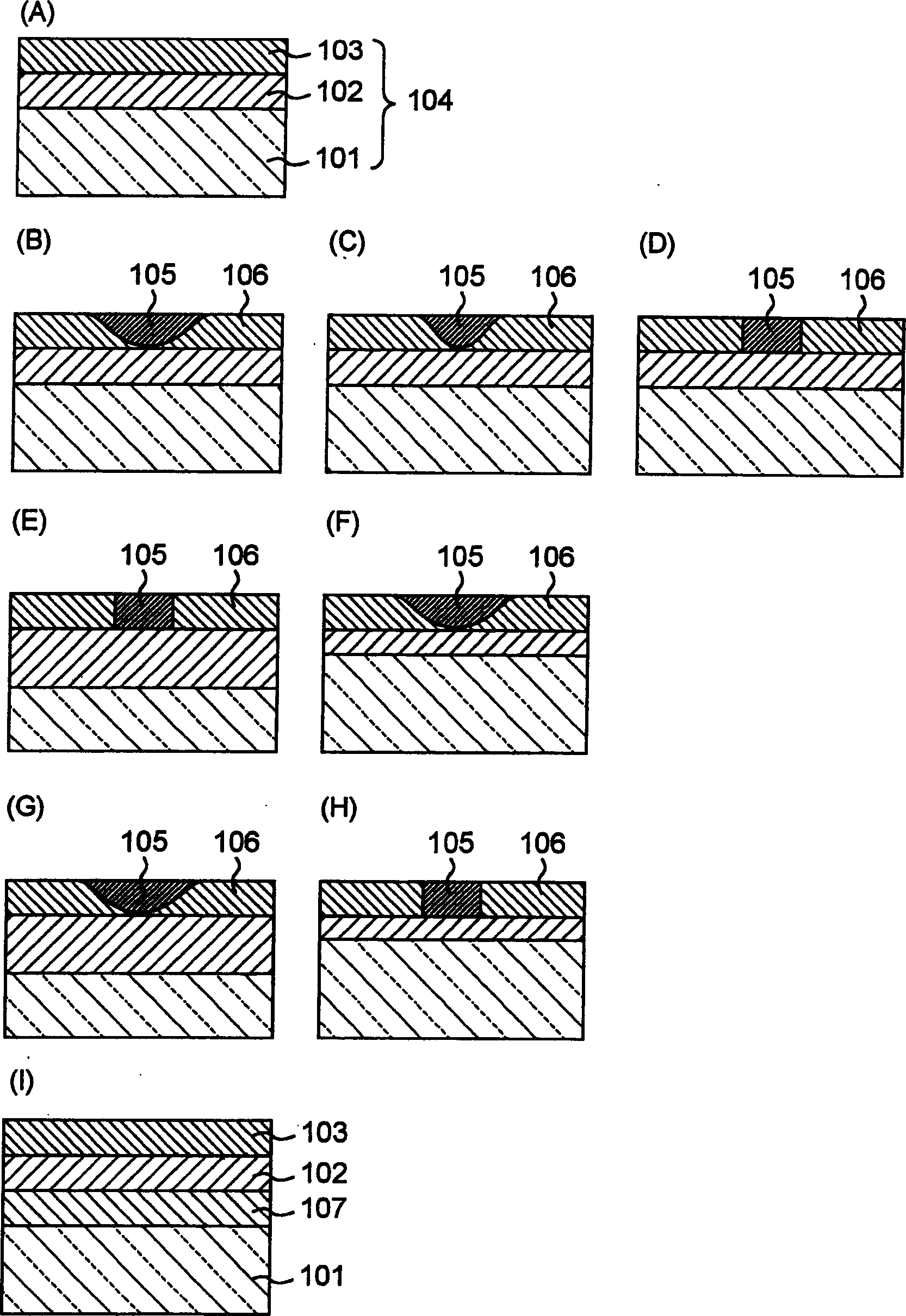
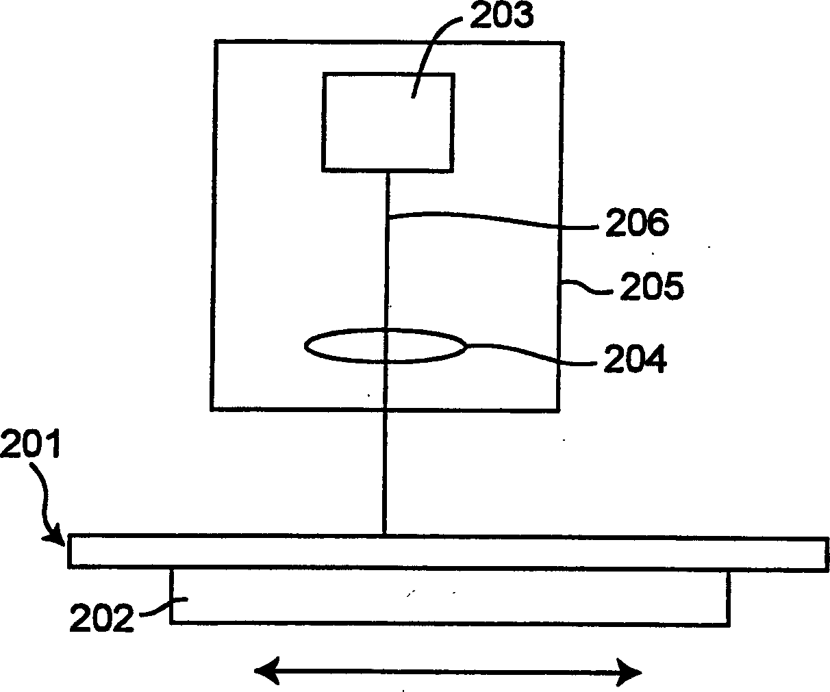
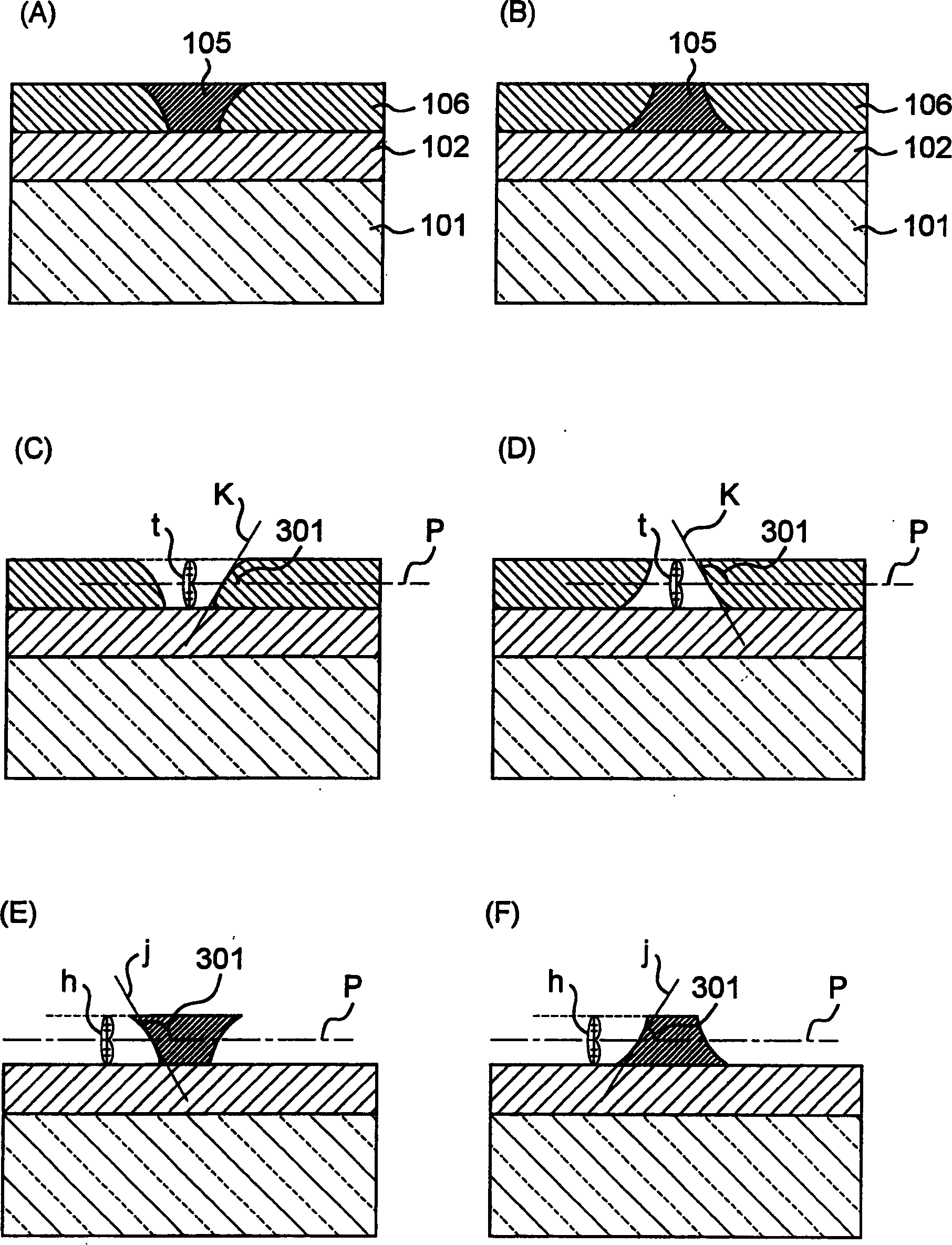
[0048] control Figure 1 to Figure 4 , as Embodiment 1, a method of manufacturing an optical information storage medium original disk using a recording original disk provided with a recording auxiliary layer between a heat-sensitive material layer and a substrate will be described. figure 1 (A) shows a cross-sectional view of an example of a recording master disk. figure 1 In the recording master disk 104 shown in (A), the substrate 101 is made of glass, silicon, or resin. On this substrate 101, a recording auxiliary layer 102 made of a material such as a dielectric or resin is formed by a method such as sputtering or centrifugal coating. A thermosensitive material layer 103 is formed on the recording auxiliary layer 102 and brought into contact with the recording auxiliary layer 102 . The heat-sensitive material layer 103 is made of a substance whose state changes due to the temperature rise caused by exposure, by methods such as sputtering or centrifugal coating. The re...
Embodiment approach 2
[0066] control Figure 5 , a second embodiment of a method of manufacturing a master disk using a recording master disk in which a recording auxiliary layer is disposed on the upper surface of the heat-sensitive material layer (the surface farther from the substrate) will be described. Figure 5 (A) shows an example of an original recording disc. The recording master disk 504 has a substrate 501 provided with a thermosensitive material layer 502 , and a recording auxiliary layer 503 provided on the thermosensitive material layer 502 . Figure 5 506 in (A) refers to the external medium (that is, the ambient gas during exposure), which is generally air. The material and manufacturing method of the substrate 501 and the heat-sensitive material layer 502 that constitute the recording master are the same as those described in the first embodiment. The recording auxiliary layer 503 may be a film formed using the materials and methods described in the related descriptions in Embodi...
Embodiment approach 3
[0073] control Figure 6 , to describe a method of manufacturing a master disk using a recording master disk in which a heat-sensitive material layer is sandwiched between two recording auxiliary layers—Embodiment 3. Figure 6 (A) shows an example of an original recording disc. The recording original disk 605 has a first recording auxiliary layer 602 disposed on its substrate 601, a heat sensitive material layer 603 is disposed on the first recording auxiliary layer 602, and a second recording auxiliary layer 604 is disposed on the heat sensitive material layer 603. . The material and manufacturing method of the substrate 601 and the heat-sensitive material layer 603 of the recording original disk constituent part are the same as those described in the first embodiment. In addition, the first recording auxiliary layer 602 and the second recording auxiliary layer 604 are also made using the materials and methods described in the first embodiment. The second recording auxilia...
PUM
| Property | Measurement | Unit |
|---|---|---|
| angle | aaaaa | aaaaa |
| thickness | aaaaa | aaaaa |
| thickness | aaaaa | aaaaa |
Abstract
Description
Claims
Application Information
 - R&D
- Intellectual Property
- Life Sciences
- Materials
- Tech Scout
- Unparalleled Data Quality
- Higher Quality Content
- 60% Fewer Hallucinations
Browse by: Latest US Patents, China's latest patents, Technical Efficacy Thesaurus, Application Domain, Technology Topic, Popular Technical Reports.
© 2025 PatSnap. All rights reserved.Legal|Privacy policy|Modern Slavery Act Transparency Statement|Sitemap|About US| Contact US: help@patsnap.com


