Self-excited switching power supply circuit

A switching power supply circuit, self-excited technology, applied in electrical components, regulating electrical variables, instruments, etc., can solve problems such as rapid discharge and increased loss of switching components

Active Publication Date: 2005-02-02
SMK CO LTD
View PDF1 Cites 6 Cited by
  • Summary
  • Abstract
  • Description
  • Claims
  • Application Information

AI Technical Summary

Problems solved by technology

[0021] On the other hand, in the primary winding 2a or FET3, there are stray capacitances between the windings or parasitic capacitances between the drain and the source. Sweep voltage charging, therefore, if the drain of FET3 (primary winding 2a side) voltage does not drop enough, that is, in the state of around 200V, it will be rapidly discharged
[0022] As a result, happens as Figure 5 A discharge current of the magnitude indicated by A in (c) increases the loss of switching elements such as FET3, and at the same time causes noise.

Method used


Image

  • Self-excited switching power supply circuit
  • Self-excited switching power supply circuit
  • Self-excited switching power supply circuit

Examples


Embodiment Construction

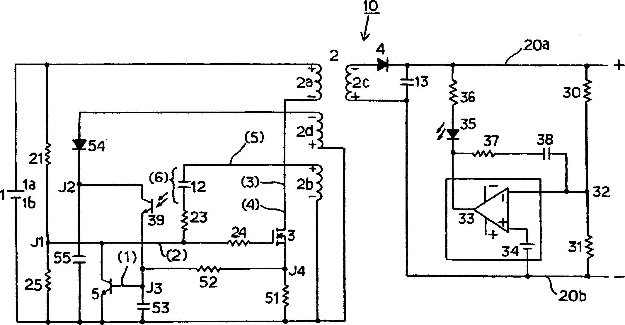
[0040] Hereinafter, an embodiment of the present invention will be described in detail with reference to the drawings. figure 1 It is a circuit diagram showing the configuration of a self-excited switching power supply circuit 10 according to an embodiment of the present invention. The self-excited switching power supply circuit 10 of the present embodiment and Figure 4 In the conventional self-excited switching power supply circuit 100 shown, the main circuits and circuit elements are common, and the same structures are denoted by the same symbols, and their descriptions are omitted.

[0041] Such as figure 1 As shown, the transformer 2 is provided with a primary winding 2a on the primary side, a first feedback winding 2b wound in the same direction as the primary winding 2a, and a second feedback winding 2d wound in the opposite direction relative to the primary winding 2a, and a secondary winding 2d on the secondary side. Output winding 2c.

[0042] The primary winding...


PUM


Abstract

The time constant of the conduction control circuit (12, 23) is set so that the gate voltage of the field effect transistor (3) for oscillation exceeds the threshold voltage VTH in the state where the polarity of the voltage of the feedback winding (2b) is reversed. When the voltage of the winding (2a) becomes lower than the power supply voltage, the oscillation field effect transistor (3) is turned on, and the stray capacitance accumulated between the primary windings (2a) or the parasitic capacitance of the oscillation field effect transistor (3) The charge is discharged slowly. Therefore, the discharge current generated when the oscillation field effect transistor (3) is turned on is reduced, and as a result, energy loss during switching is small and noise is not generated.

Description

technical field [0001] The present invention relates to a self-excited switching power supply circuit, in particular to a flyback type self-excited switching power supply circuit which releases the energy accumulated in the transformer from the secondary output winding when the excitation current of the primary winding of the transformer is stopped. Background technique [0002] As a stable power supply, switching power supply circuits are used in battery chargers or AC adapters, etc. The driving method (switching method) of the switching element is roughly divided into two types: the self-excited oscillation method and the self-excited oscillation method. The self-excited oscillation method uses the voltage generated in the feedback winding of an inductance component such as a transformer as a drive signal to positively feed back to the switching element. The control terminal for oscillation action. [0003] As such a self-excited switching power supply circuit, known such...

Claims


Application Information

Patent Timeline
Patent Type & Authority Applications(China)
IPC IPC(8): H02M3/28H02M3/338
CPCH02M3/3381
Inventor 饴井俊裕
Owner SMK CO LTD
Why Eureka
Try Eureka