Waste gas processing system

A waste gas treatment and waste gas technology, applied in separation methods, dispersed particle separation, chemical instruments and methods, etc., can solve the problems of inability to completely remove sulfur trioxide, inability to fully adsorb and remove coal dust, and increase equipment costs.

Inactive Publication Date: 2005-02-09
MITSUBISHI HEAVY IND LTD
View PDF0 Cites 8 Cited by
  • Summary
  • Abstract
  • Description
  • Claims
  • Application Information

AI Technical Summary

Problems solved by technology

[0006] However, in the above-mentioned conventional waste gas treatment system, due to sulfur trioxide (SO 3 ) content is high, so in the dry electrostatic precipitator 004, sulfur trioxide is converted into ammonium sulfate by adding ammonia to absorb and remove, so a large amount of ammonia is needed, and there is a problem of increased processing costs
In addition, the dry electric dust collector 004 originally absorbs the coal dust in the exhaust gas, but because it absorbs a large amount of ammonium sulfate, it has the disadvantage of not being able to fully absorb and remove the coal dust
[0007] Also, in the dry electrostatic precipitator 004, the sulfur trioxide in the waste gas cannot be completely removed, and on the other hand, the desulfurization device 006 is to adsorb and remove the sulfur dioxide (SO 2 ), a wet electric dust collector 007 is installed on its downstream side to absorb and remove sulfur trioxide remaining in the exhaust gas
Therefore, two dust collectors 004 and 007 are required, so there is a problem that the size of the system increases and the equipment cost increases

Method used


Image

  • Waste gas processing system
  • Waste gas processing system
  • Waste gas processing system

Examples


Embodiment Construction

[0018] Hereinafter, embodiments of the present invention will be described in detail based on the drawings.

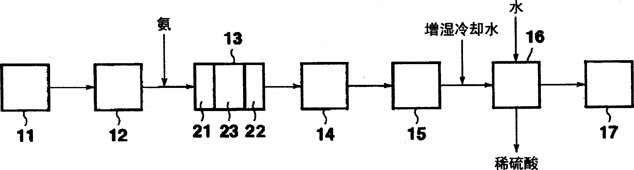
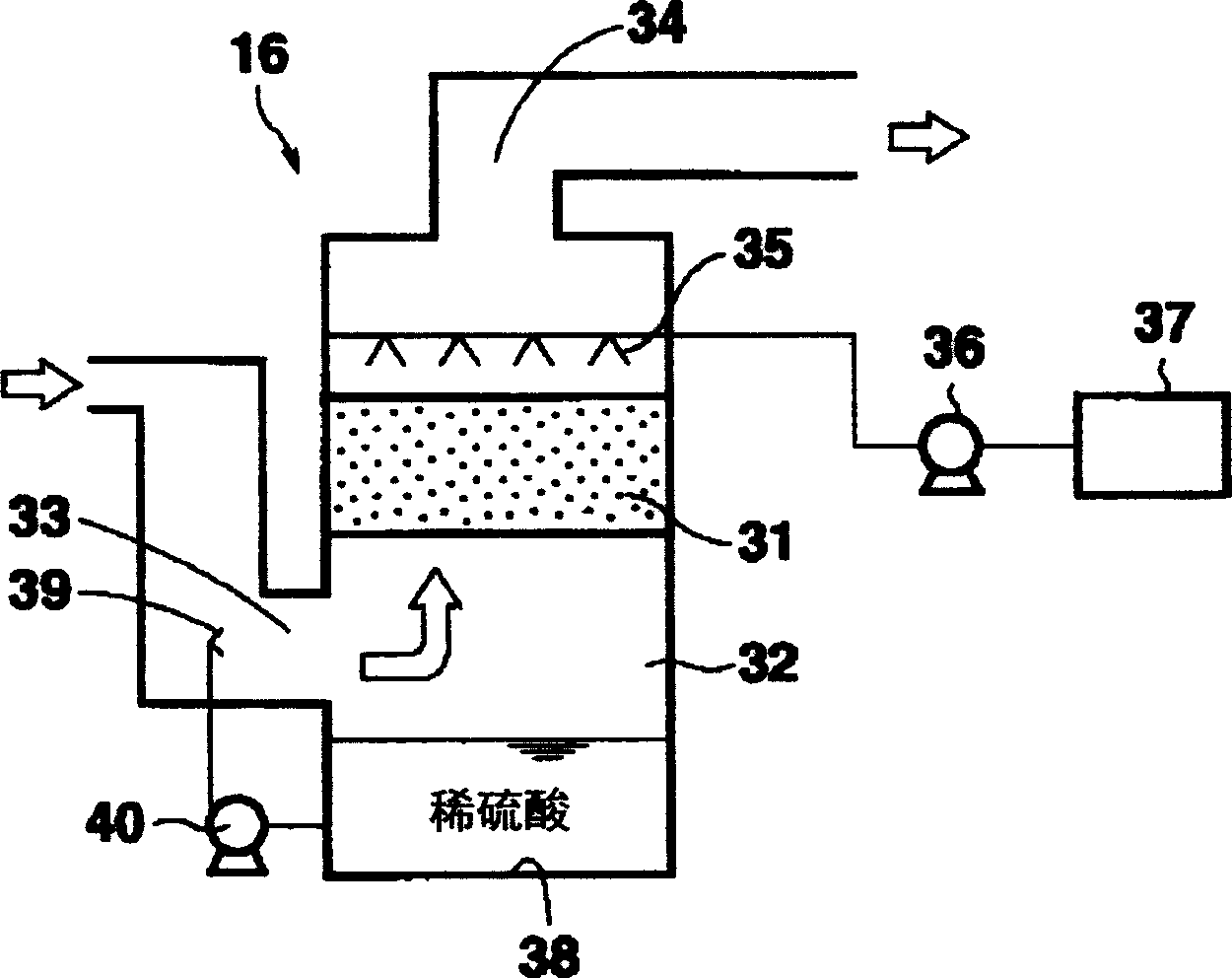
[0019] exist figure 1 A schematic configuration of an exhaust gas treatment system according to an embodiment of the present invention is shown in figure 2 The schematic configuration of the ACF desulfurization unit is shown in .

[0020] The exhaust gas treatment system of this embodiment is used in boiler facilities (burning furnaces, incinerators) using fuels containing high sulfur components such as petroleum coke and Ori-mulsion.

[0021] Such as figure 1 As shown, the waste gas treatment system of this embodiment is that for the waste gas discharged from the boiler 11, a high-temperature dry electric dust collector 12, a denitrification device 13, an air heater 14, an exhaust fan 15, an ACF desulfurization device 16, and a chimney are continuously arranged. 17 and constituted.

[0022] The exhaust gas of about 200-400 degreeC is supplied from the boiler 11...


PUM


Abstract

In an exhaust gas treatment system, dust in a high temperature exhaust gas is caught by a high temperature dry electrostatic precipitator, a nitrogen oxide NO2 in the exhaust gas is removed by denitration means, then the exhaust gas is cooled by an air heater, and the exhaust gas is passed through an activated carbon fiber layer of activated carbon treatment means to remove sulfur oxides SO2 and SO3 contained in the exhaust gas. The exhaust gas treatment system reduces the costs of treatment and equipment, and downsizes the system.

Description

technical field [0001] The present invention relates to an exhaust gas treatment system for purifying and treating high-temperature exhaust gas discharged from boiler equipment and the like using fuel containing high sulfur components. Background technique [0002] image 3 A schematic configuration of a conventional exhaust gas treatment system is shown. Such as image 3 As shown, in the conventional waste gas treatment system, for the waste gas discharged from the boiler 001, the denitration device 002, the air heater 003, the dry electric dust collector 004, the exhaust fan 005, the desulfurization device 006, and the wet electric dust collector are continuously arranged. 007 and chimney 008. [0003] Therefore, the exhaust gas discharged from the boiler 001 is first denitrated by adding ammonia to the nitrogen oxides in the exhaust gas in the denitrification device 002 . Next, after being cooled below the specified temperature in the air heater, it is sent to the dry e...

Claims


Application Information

Patent Timeline
Patent Type & Authority Applications(China)
IPC IPC(8): B01D53/50B01D53/56B01D53/74B01D53/77B01D53/86
CPCB01D53/8631B01D53/86
Inventor 小林敬古荒川善久横式龙夫小田直芳大西利幸
Owner MITSUBISHI HEAVY IND LTD
Why Eureka
Try Eureka