

Laser quenching hardening treatment method for cutter and die cutting edge
A technology of hardening treatment and laser quenching, applied in the field of machining, can solve the problems of easy melting of sharp corners, unusable tools and molds, short heating time, etc., to achieve the effect of short heating time, small deformation and easy operation
- Summary
- Abstract
- Description
- Claims
- Application Information
AI Technical Summary
Problems solved by technology
Method used
Image

Examples
Embodiment 1
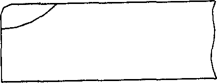
[0013] Embodiment 1: the processing process of the sheet metal garden piece cutter is: a, first put the sheet material garden sheet cutter on the laser processing machine workbench, and according to the requirements of use, a certain knife face of the cutting edge to be processed is horizontally upward Put it on the plane of the machine tool table; b. In the range of 10mm away from the cutting edge and parallel to the cutting edge, evenly coat the laser heat treatment light-absorbing coating; c. Adjust the laser beam focus of the Φ5mm spot to On the knife face of the plate garden slice cutter, the beam axis is perpendicular to the plate garden slice cutter face; and the vertical distance between the beam center and the cutting edge is 2.6mm. d, the laser beam is scanned and heated on the plane of the plate cutter along the direction parallel to the cutting edge. As shown in Figure 3, the laser treated hardened structure, the hardened layer depth at the cutting edge is greater ...
Embodiment 2
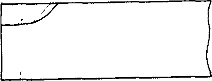
[0014] Embodiment 2: the processing process of the sheet metal garden piece cutter is: a, at first put the sheet material garden sheet cutter on the laser processing machine workbench, and according to the requirements of use, a certain knife face of the cutting edge to be processed is horizontally upward Place it on the plane of the machine tool table; b. Evenly coat the laser heat treatment light-absorbing coating within the range of 15mm away from the cutting edge and parallel to the cutting edge; c. Adjust the laser beam focus of the Φ5mm spot to On the knife face of the plate garden slice cutter, the beam axis is perpendicular to the plate garden slice cutter face; and the vertical distance between the beam center and the cutting edge is 3.7mm. d, the laser beam is scanned and heated on the plane of the plate cutter along the direction parallel to the cutting edge. As shown in Figure 3, the laser treated hardened structure, the hardened layer depth at the cutting edge is ...
Embodiment 3
[0015] Embodiment 3: The sheet material blanking die is processed through the following steps: a. Put the sheet material blanking die on the laser processing machine workbench, and according to the requirements of use, a certain surface of the sheet material blanking die edge is horizontally upward Put it on the plane of the machine tool table; b. On the surface of the sheet blanking die, within the range of 12mm away from the cutting edge and parallel to the cutting edge, evenly coat the laser heat treatment light-absorbing coating; c. Adjust the laser beam focus of the Φ5.5mm spot On the cutting edge surface of the sheet material blanking die, the beam axis is perpendicular to the cutting edge surface of the sheet material blanking die. The vertical distance between the center of the beam and the cutting edge is 3.0mm; d. The laser beam is scanned and heated on the plane of the plate blanking mold along the direction parallel to the cutting edge. The laser power: 1500W, the l...
PUM
| Property | Measurement | Unit |
|---|---|---|
| Width | aaaaa | aaaaa |
Abstract
Description
Claims
Application Information