
Automobile cooling-fan driving mechanism assembly

A driving mechanism and automobile cooling technology, which is applied to the cooling of engine components, machines/engines, and engines, can solve the problems of unstable operating temperature of the engine, large noise and exhaust pollutants, and increased engine volume, so as to achieve sufficient Adaptability options, reduction of noise and exhaust pollutants, and the effect of reducing fuel consumption

Inactive Publication Date: 2005-02-16
王永钦
View PDF0 Cites 11 Cited by
  • Summary
  • Abstract
  • Description
  • Claims
  • Application Information

AI Technical Summary

Problems solved by technology

With the development of large-scale vehicles, the requirements for engine power continue to increase, which will inevitably increase the volume of the engine, which brings great difficulties to the rear arrangement.
Therefore, the space utilization rate of the existing technology is low, the engine operating temperature is not stable, the fuel consumption is high, and the noise and exhaust pollutants are relatively large.

Method used


Image

  • Automobile cooling-fan driving mechanism assembly
  • Automobile cooling-fan driving mechanism assembly
  • Automobile cooling-fan driving mechanism assembly

Examples


Embodiment 1

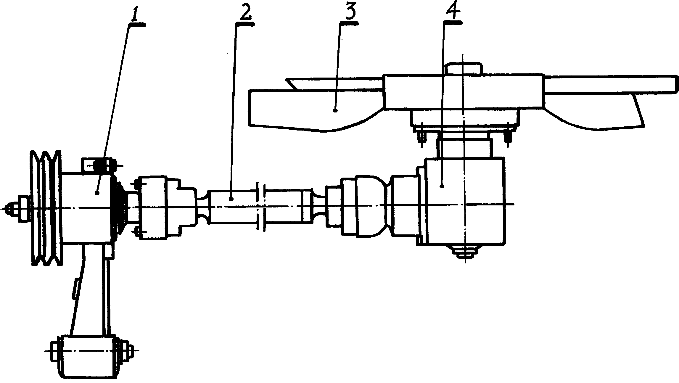
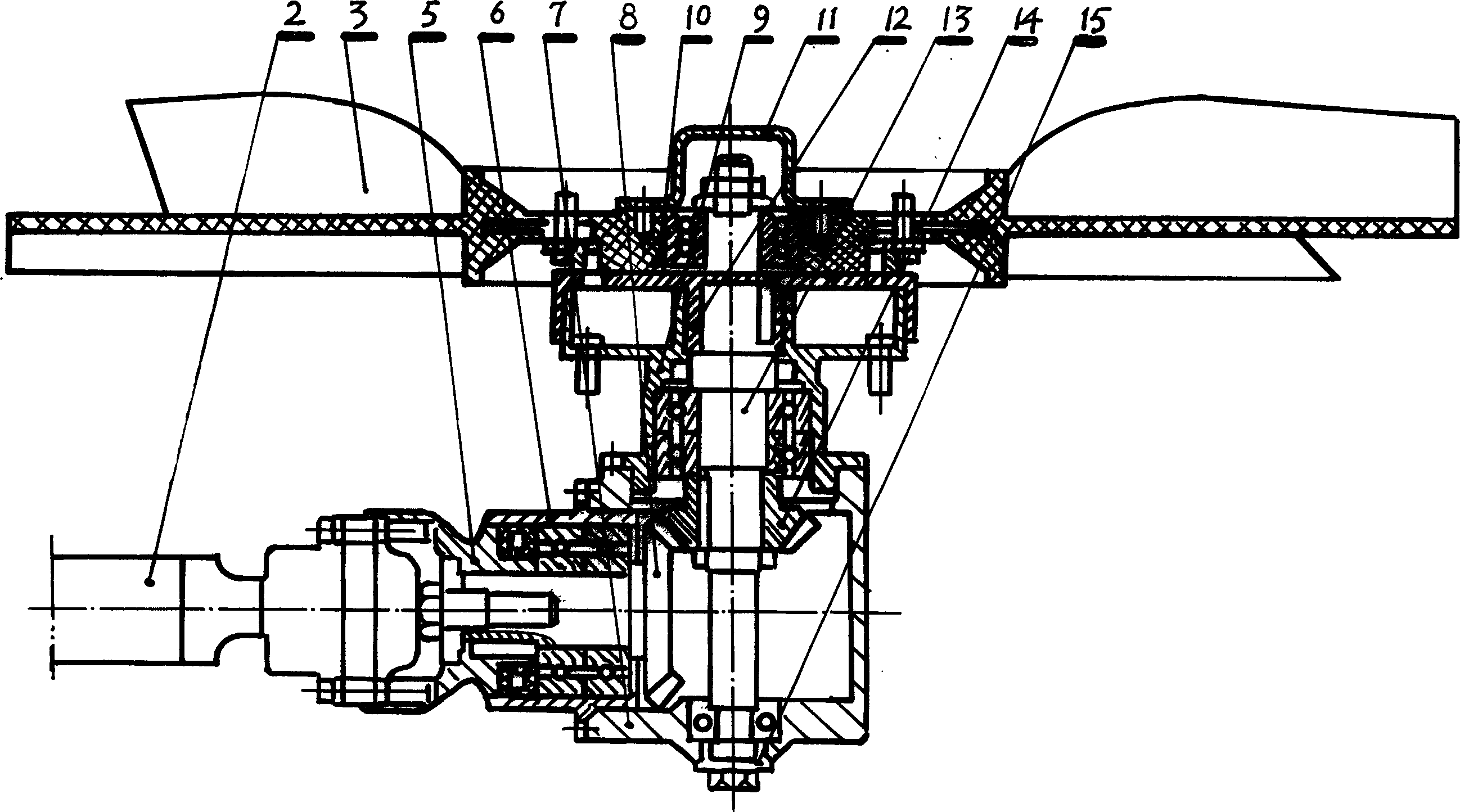
[0015] The first embodiment does not install the magnetic clutch 21, and is an economical fan drive mechanism assembly. The large bevel gear 8 and the small bevel gear 14 have undergone high-precision machining and strict heat treatment, and splash lubrication is carried out when the gears rotate to ensure effective heat dissipation and reduce noise of the gear pair. The transmission shaft assembly 2 adopts a telescopic ball cage universal joint, which has a simple and concise structure, small sliding resistance and high transmission efficiency. The mechanism assembly can adopt a fan with a large diameter of 560-720mm, which is very convenient for installation and debugging.

Embodiment 2

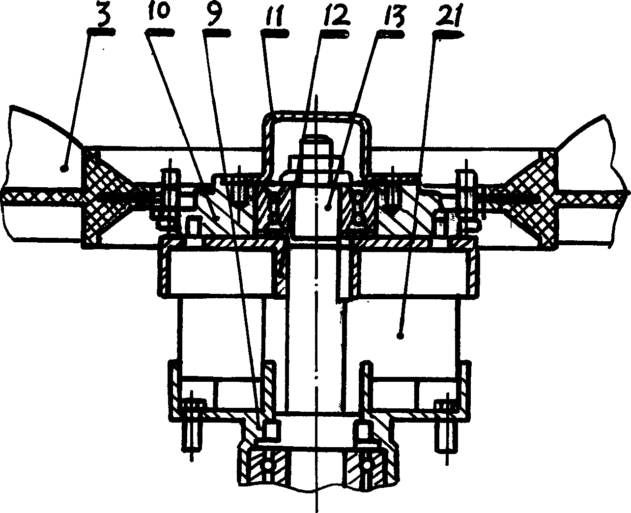
[0016] Embodiment 2 is equipped with a magnetic clutch 21, which is a luxurious fan drive mechanism assembly. The magnetic clutch 21 works under the condition of no torsional force and drag torque. Through the temperature sensor in the cooling circuit, the rotation direction of the fan can be changed accurately and quickly, which has a very high efficiency and makes the fan have good adaptability, thus effectively reducing fuel consumption and reducing noise.

[0017] The Magnetic Clutch 21 is available in three different sizes:

[0018] Level 1 speed magnetic clutch 21: With the breaking torque of the magnetic clutch 21, it acts through bearing friction, and the fan rotates at a speed of 100 revolutions per minute.

[0019] 2-stage speed magnetic clutch 21: With the torque off of the magnetic clutch 21, the fan blades rotate at a speed of 1200 revolutions per minute driven by the permanent magnet system without contact and friction.

[0020] 3-speed magnetic clutch 21: With...


PUM


Abstract

This invention relates to the cooling of the engine of the engine of a locomotive, especially to the pump pumping cooling air, such as the driving device of a fan, the unit assembly of its driving system is composed of a drive shaft assembly, a mid wheel assembly, fan driver assembly and a fan assembly, the fan driver assembly includes a box, an upper flange, a flange connection disk, the mid wheel assembly includes a base fixing frame and a support, the fan driver assembly also includes a gear shaft set in the box and the flange connection disk, a fan connector and a small cone gear fixed on the gear shaft, a big cone gear tothed with the small one and a magnetic clutch is possible mounted between the flange connection disk and the fan connector.

Description

Technical field [0001] The invention relates to the cooling of motor vehicle engines, in particular to pumps for pumping cooling air, such as drives for fans. Background technique [0002] At present, in the cooling system of the known motor vehicle rear engine, as the fan that helps the cooling water tank to dissipate heat, its power is directly transmitted from the engine crankshaft through the V-belt. At this time, the cooling fan shaft must be parallel to the engine crankshaft. With the development of vehicles in the direction of large-scale, the requirements for engine power continue to increase, which will inevitably increase the volume of the engine, which brings great difficulties to the rear arrangement. Therefore, the space utilization rate of the prior art is relatively low, the operating temperature of the engine is not stable, the fuel consumption is high, and the noise and exhaust pollutants are relatively large. Contents of the invention [0003] In order ...

Claims


Application Information

Patent Timeline
Patent Type & Authority Applications(China)
IPC IPC(8): F01P5/04F02B67/04F02B67/06
Inventor 王永钦
Owner 王永钦
Learn More