Power supply circuit and semiconductor integrated circuit apparatus
A technology of power supply circuit and voltage generation circuit, which is applied in the directions of data processing power supply, electric variable adjustment, electric digital data processing, etc. It can solve the problems of increased base area, increased manufacturing cost, and inability to obtain low current consumption effects, etc., and achieves reduction Effects of current consumption and stable power supply voltage
- Summary
- Abstract
- Description
- Claims
- Application Information
AI Technical Summary
Problems solved by technology
Method used
Image
Examples
no. 1 example
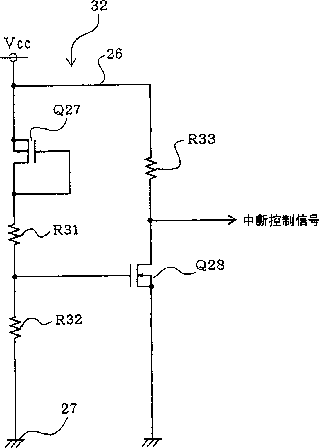
[0054] A first embodiment according to the present invention will be described with reference to FIGS. 1 and 2 .
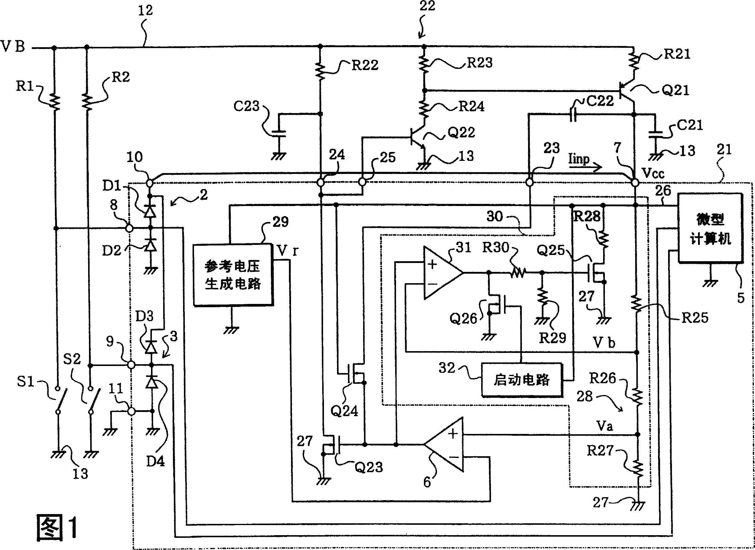
[0055] FIG. 1 is a diagram showing a configuration of a power supply circuit and an input protection circuit for an input port of an ECU (Electronic Control Unit) of a vehicle. In FIG. 1, the same constituent elements as those in FIG. 13 will be denoted by the same reference numerals.
[0056] The IC 21 for control (equivalent to semiconductor integrated circuit equipment) includes a microcomputer 5, input protection circuits 2, 3 for input ports of the microcomputer 5, and a control circuit of a power supply circuit 22, etc. IC 21 is mounted on a board (not shown) housed in the ECU case. As mentioned above, the microcomputer (equivalent to the load) can work in the low power consumption mode and the normal mode.
[0057] When the battery voltage VB is applied to each signal input terminal 8, 9, each input protection circuit 2, 3 fixes the input voltage at the p...
no. 2 example
[0082] Next, a second embodiment of the present invention will be described with reference to FIG. 3 .
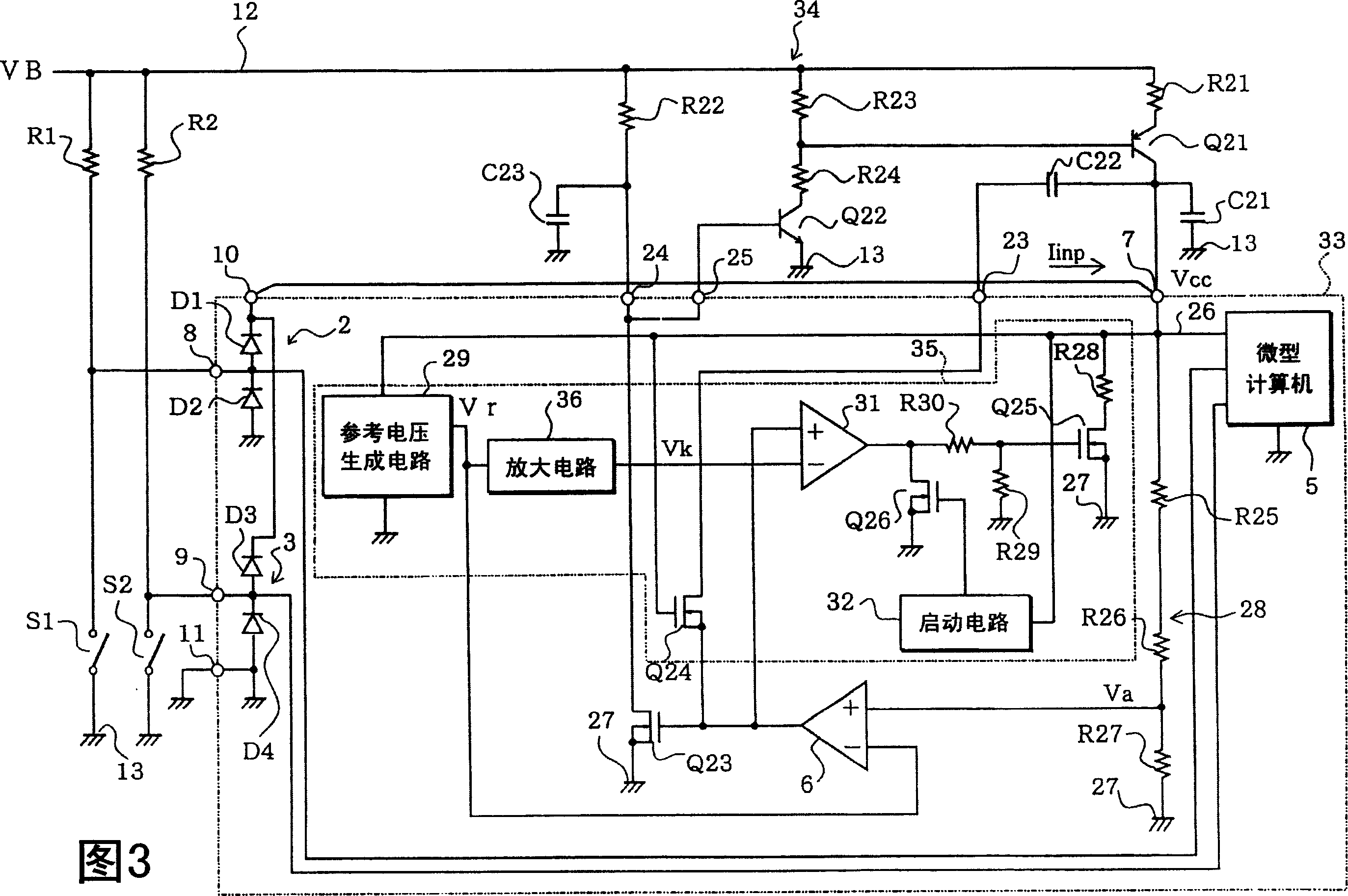
[0083] FIG. 3 shows the structure of a power supply circuit and the structure of an input protection circuit for an input port, and the same constituent elements as those in FIG. 1 are denoted by the same reference numerals. In the structural part of the current sinking circuit 35 of the power supply circuit 34 installed in the IC 33, this embodiment is partly different from the first embodiment, that is, instead of the voltage dividing circuit 28, the current sinking circuit 35 is equipped with a reference voltage generating circuit 29 and amplifying circuit 36. The amplification circuit 36 amplifies the reference voltage Vr input from the reference voltage generation circuit 29 to generate a constant reference voltage Vk (for example, 1.75V). Therefore, the reference voltage Vk thus generated is applied to the inverting input terminal of the operational amplifier 31 . ...
no. 3 example
[0086] Next, a third embodiment of the present invention will be described with reference to FIG. 4 .
[0087] FIG. 4 shows the structure of a power supply circuit and the structure of an input protection circuit for an input port, and the same constituent elements as those in FIG. 1 are denoted by the same reference numerals. This embodiment differs from the first embodiment in the structural part of the current sink circuit 39 of the power supply circuit 38 mounted in the IC 37.
[0088] That is, a series circuit including a resistor R34, an N-channel type MOS transistor Q29 (equivalent to a third transistor) and a resistor R35, and a series circuit including resistors R36 and R37 are connected between the reference voltage generating circuit 29 and the ground. between line 27. A common connection point between the resistor R34 and the drain of the transistor Q29 and a common connection point between the resistors R36 and R37 are connected to the inverting input terminal an...
PUM
 Abstract
Description
Claims
Application Information
 - R&D
- Intellectual Property
- Life Sciences
- Materials
- Tech Scout
- Unparalleled Data Quality
- Higher Quality Content
- 60% Fewer Hallucinations
Browse by: Latest US Patents, China's latest patents, Technical Efficacy Thesaurus, Application Domain, Technology Topic, Popular Technical Reports.
© 2025 PatSnap. All rights reserved.Legal|Privacy policy|Modern Slavery Act Transparency Statement|Sitemap|About US| Contact US: help@patsnap.com


