Method and device for correcting image geometrical error in laser phototype setter

A laser imagesetter, a technology for correcting images, applied in photoelectric typesetting devices, automatic power control, printing and other directions, can solve problems such as difficult adjustment, defects in flat screen grayscale images, etc., to overcome errors, low cost, and methods. simple effect

Active Publication Date: 2005-03-02
深圳市东方宇之光科技股份有限公司
View PDF0 Cites 1 Cited by
  • Summary
  • Abstract
  • Description
  • Claims
  • Application Information

AI Technical Summary

Problems solved by technology

On the other hand, when the multi-channel scanning technology is used, the influence of the helix angle becomes significant, and it is difficult to adjust during installation.
Especially in the machine design with many channels and adjustable resolution, the influence of helix angle cannot be eliminated by mechanical means
[0003] If software means are used to compensate and correct the structural error of the device when the raster graphics are generated, the accuracy of the correction is calculated in terms of image points, so that steps will be generated on the edges of the lines, and will also appear in flat screen grayscale images. flaw

Method used


Image

  • Method and device for correcting image geometrical error in laser phototype setter
  • Method and device for correcting image geometrical error in laser phototype setter
  • Method and device for correcting image geometrical error in laser phototype setter

Examples


Embodiment Construction

[0026] The present invention will be further described below in conjunction with accompanying drawing:

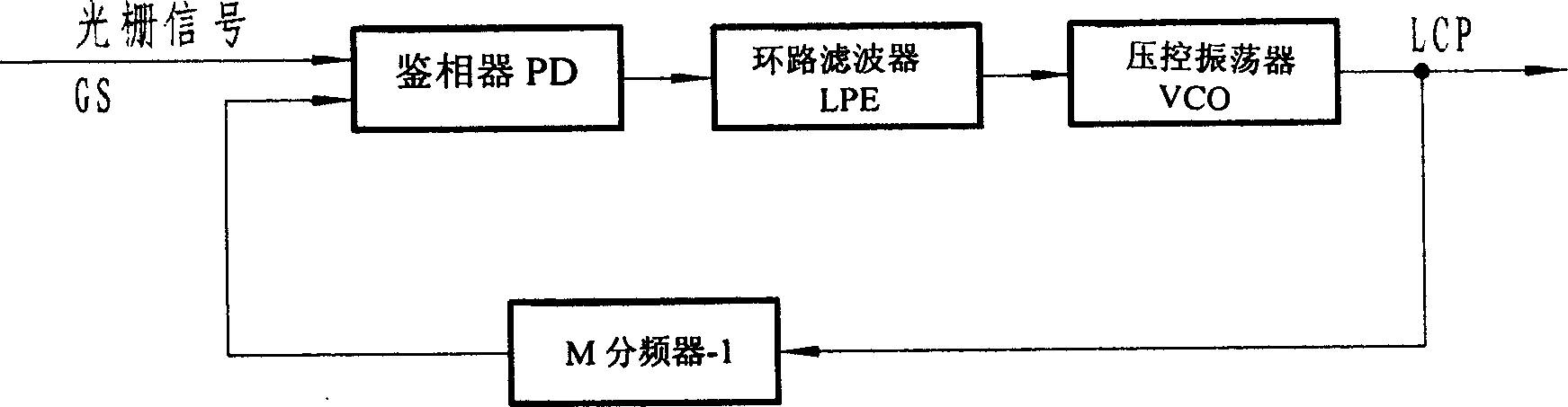
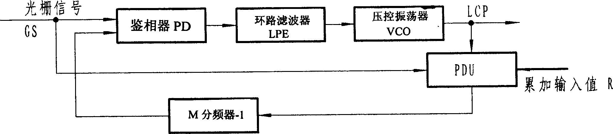
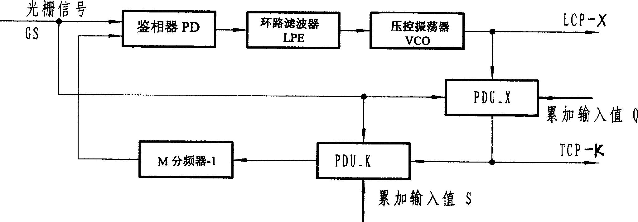
[0027] The solution proposed by the present invention is to insert two programmable fractional frequency division units PDU-X and PDU-K which can realize frequency multiplication and fractionation into the feedback link of the traditional phase-locked loop. see image 3 .

[0028] A complete system structure of the present invention is: a phase-locked loop made up of phase detector PD, loop filter LPE, voltage-controlled oscillator VCO, its feedback loop is a frequency divider whose modulus length is M; Two "programmable fractional frequency division units" (PDU-X and PDU-K) are added to the phase frequency multiplication system. In order to coordinate with them, a cycle counter, line length counter, post divider, and address Counters, calibration memory, etc. see Image 6 .

[0029] The present invention is further explained below:

[0030] The present invention aims...


PUM


Abstract

The method and device for correcting geometrical error of image in laser phototypesetting. The method relates to grating frequency-doubling phase locked loop and has main technology of inserting two programmable fractional frequency dividing units PDU-X and PDU-K into the feedback link of the phase locked loop. The device for the method is one phase locked loop comprising phase discriminator PD, loop filter LPE and voltage controlled oscillator VCO, and with feedback loop being one frequency divider with module length M. The phase locked frequency-doubling system has two increased programmable fractional frequency dividing units PDU-X and PDU-K as well as corresponding period counter, line length counter, post-frequency divider, address counter, correction memory, etc.

Description

technical field [0001] The invention relates to image output equipment such as an optical plotter and a laser phototypesetter, and mainly refers to a method and a device for correcting image geometric errors in a laser phototypesetter. Background technique [0002] In image output devices such as optical plotters and laser imagesetters, there are extremely high requirements for the geometric accuracy of graphics. This requirement is generally guaranteed by high-precision machining. For example, drum-type laser graphics equipment often requires that the cylindricity error of the drum (with a diameter of several hundred millimeters) is not greater than 0.01mm. In addition, there are extremely high requirements for the precision of the screw and the guide rail. On the other hand, when the multi-channel scanning technology is used, the influence of the helix angle becomes significant, and it is difficult to adjust during installation. Especially in the machine design with man...

Claims


Application Information

Patent Timeline
Patent Type & Authority Applications(China)
IPC IPC(8): B41B19/00H03L7/08
Inventor 刘晓东
Owner 深圳市东方宇之光科技股份有限公司
Why Eureka
Try Eureka