Nano laser measuring rule and subdivision method for nano measurement realization

A nano-laser and laser technology, applied to the structure/shape of lasers, laser components, optical resonators, etc., can solve the problems of four-zone unevenness, keeping the same, four-zone unevenness, etc.

Inactive Publication Date: 2005-04-06
TSINGHUA UNIV
View PDF1 Cites 10 Cited by
  • Summary
  • Abstract
  • Description
  • Claims
  • Application Information

AI Technical Summary

Problems solved by technology

2. The error caused by the unevenness of the four regions
Strictly speaking, it is difficult to distinguish the four power tuning curves of the "displacement self-sensing HeNe laser system" completely equally. In particular, when the measurement range becomes larger, the lon

Method used


Image

  • Nano laser measuring rule and subdivision method for nano measurement realization
  • Nano laser measuring rule and subdivision method for nano measurement realization
  • Nano laser measuring rule and subdivision method for nano measurement realization

Examples


Embodiment 1

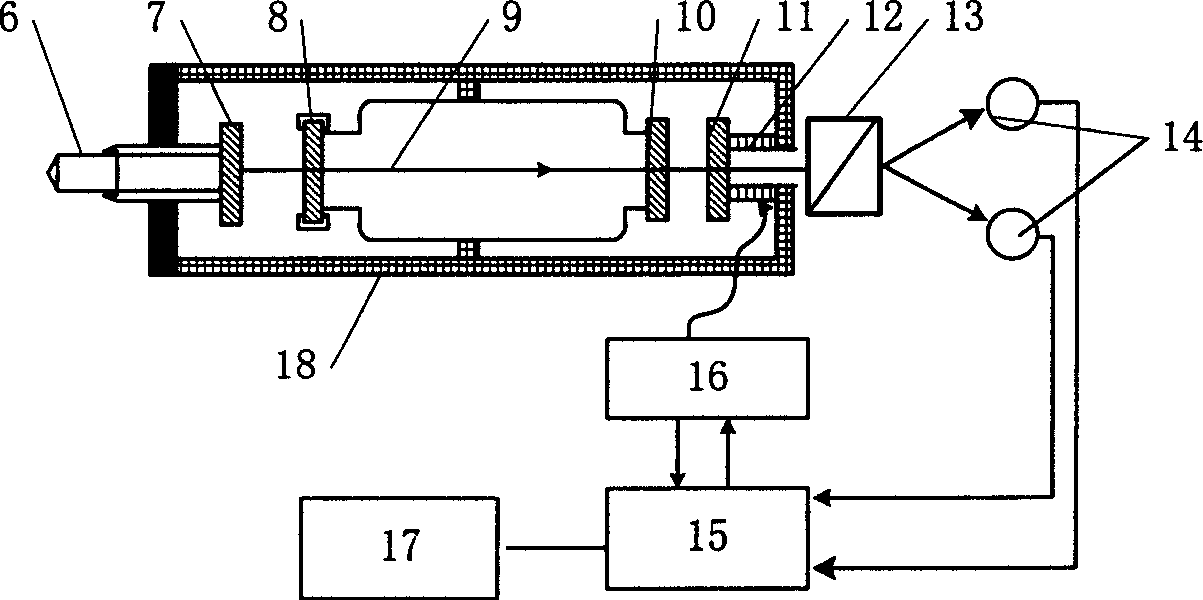
[0066] Embodiment 1; ( figure 2 )

[0067] The cat's-eye reverse mirror 7 on the movable measuring rod 6 (which is in contact with the object to be measured and moves due to displacement) passes through the anti-reflection windows 8 and 10, together with the gain tube 9 and the concave output mirror 11 to form a HeNe laser with a full external cavity. The force ring on the anti-reflection window 8 makes it a stress birefringent element, which turns the single-frequency laser into orthogonally polarized light with two frequencies and outputs it from 11 . The concave output mirror 11 is adhered to a micro-displacement piezoelectric sensor, that is, PZT, 12, and can be moved slightly. The orthogonally polarized light is split by the polarizing beam splitter 13 and projected onto two photodetectors 14 respectively. In circuit 15, the optical signal is converted into an electrical signal and processed. During the measurement process, 15 can send a scanning signal to drive the P...

Embodiment 2

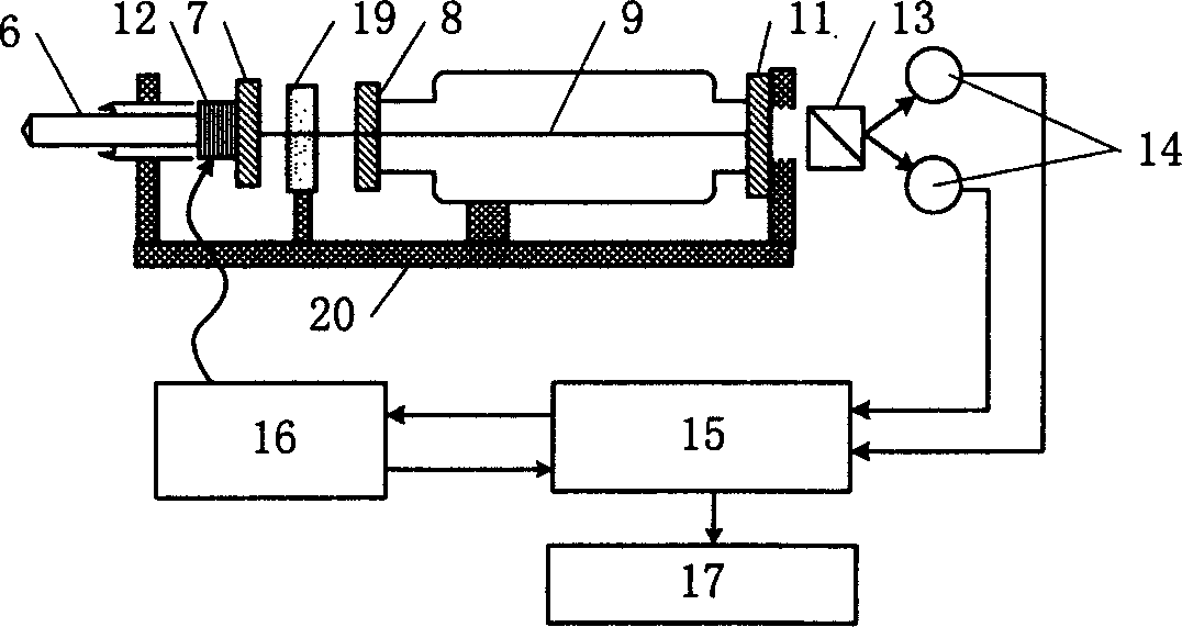
[0068] Embodiment 2: ( image 3 )

[0069] Same as Example 1, the cat's-eye reverse mirror 7 on the movable measuring rod 6 constitutes a half-cavity HeNe laser through the anti-reflection window 8, the gain tube 9 and the concave output mirror 11. and figure 2 The difference is that the frequency splitting of the laser is not caused by the stress birefringence but by the crystal quartz19. The PZT 12 is not connected with the concave output mirror 11 but adhered between the measuring rod 6 and the cat's eye 7 . The laser beam is also split by the polarization beam splitter 13 and projected onto the photodetector 14 . Circuit 15 processes the optical signal, calculates the measurement result and sends 17 to display the output. A high voltage amplifier 16 is controlled by 15 to drive the PZT 12 . Except for the circuit part, all components of the system are installed on the tablet support 20 .

[0070] For the specific block diagram of circuit 15, see Figure 4 , see the...


PUM


Abstract

The invention provides a nanometer laser measurement rule and its realization close method and belongs to laser fine measurement technique field and is characterized by the following: it is based on the displacement sensor HeNe laser system using dopal as chamber lens and adds a fine micro displacement piezoelectricity sensor PZT which can alter the chamber length together with the subject to be measured. The output crossed polarized light goes through the polarized splitter lens and shoots on two photoelectric detectors and is under the large number and small number processes by the following circuit to get and output the measurement results. It eliminates the current errors in current technique and counts the power polarized curve cycles number so to achieve the high accuracy and resolution.

Description

technical field [0001] The invention belongs to the technical field of precision measurement based on laser. Background technique [0002] The Chinese patent "Displacement self-sensing HeNe laser system and its realization method" (ZL 199103514.3) uses several laser physical phenomena, such as laser frequency splitting phenomenon, laser mode competition phenomenon, laser power tuning phenomenon, etc., to convert a laser longitudinal mode The interval is divided into 4 light-emitting regions with equal width and different polarization states (o-light region, o-light and e-light coexistence region, e-light region, no-light region), so that an ordinary HeNe laser becomes a different It is a relatively simple displacement sensing instrument that uses interference phenomenon but has self-calibration function. The method has a displacement measurement resolution of λ / 8 (λ / 8 is 79 nm for a HeNe laser with a wavelength of 0.6328 μm). [0003] Chinese invention patent application "...

Claims


Application Information

Patent Timeline
IPC IPC(8): G01B11/02H01S3/08H01S3/223
Inventor 杜文华张书练李岩
Owner TSINGHUA UNIV
Why Eureka
Try Eureka