Leakage sensor and leakage detection system

A detection system, sensor technology, applied in the direction of detecting the appearance of fluid at the leak point, using liquid/vacuum for liquid tightness measurement, testing machine/structural parts, etc. Inability to be practical and other problems to achieve the effect of improving reliability

Inactive Publication Date: 2005-05-04
通电株式会社
View PDF2 Cites 21 Cited by
  • Summary
  • Abstract
  • Description
  • Claims
  • Application Information

AI Technical Summary

Problems solved by technology

[0006] However, (A) as a cleaning agent/solvent, for example, has 6×10 or less when detected at 20°C -2 In the case of leakage of liquids with low surface tension of N/m, especially when detecting low-molecular chlorofluorocarbons (CFCs) and halons that do not contain chlorine and bromine, the surface tension is less than or equal to 3× at 20°C 10 -2 In the case of leakage 2a of a liquid with a low surface tension of N/m, the leakage forms a very thin layer and spreads, for example, as Image 6 As shown in (B), it spreads uniformly and rapidly in the form of a thin film layer with a thickness d1 of 0.5 mm or less in the leaking layer, and can easily penetrate even into very narrow gaps of 0.1 mm or less. , Therefore, the leaked liquid first penetrates into the gap d2 (Image 6 (C)), it takes a long time for the leaked liquid to spread to the retainer, and as a result, there is a problem that detection of a small amount of liquid leakage cannot be performed at all or the detection of liquid leakage is delayed
[0007] (B) In addition, at present, the leakage sensor has the following problem: because it performs "OR" operation on the alarm digital output of multiple leakage sensors, for each specified group, the alarm output is uniformly performed through the sequence generator or the main machine, etc. , Therefore, when the alarm of abnormal liquid leakage detection is output, in fact, the maintainer of the system such as the factory can not immediately determine the location of the liquid leakage for the sensor where the sensor is installed to detect the liquid leakage; the liquid leakage sensor is generally installed on the base The lowest part of the system such as the surface or the leakage storage plate, on the other hand, under the use environment conditions such as various system structural components erected in the space above it, the LED and other light-emitting alarm display components installed on the leakage sensor itself In the case of abnormal liquid leakage, it is generally difficult to visually identify it, and it is difficult to determine the location of the leakage
[0008] (C) Furthermore, in liquid leakage detection systems such as Patent Document 2, in general, the person who installs the liquid leakage sensor has nothing to do w

Method used


Image

  • Leakage sensor and leakage detection system
  • Leakage sensor and leakage detection system
  • Leakage sensor and leakage detection system

Examples


Embodiment 1

[0066] Below, refer to Figure 1 to Figure 6 , the case where the liquid leakage detection system of the present invention is applied to a coating and developing device for semiconductor wafers (hereinafter referred to as wafers) will be described.

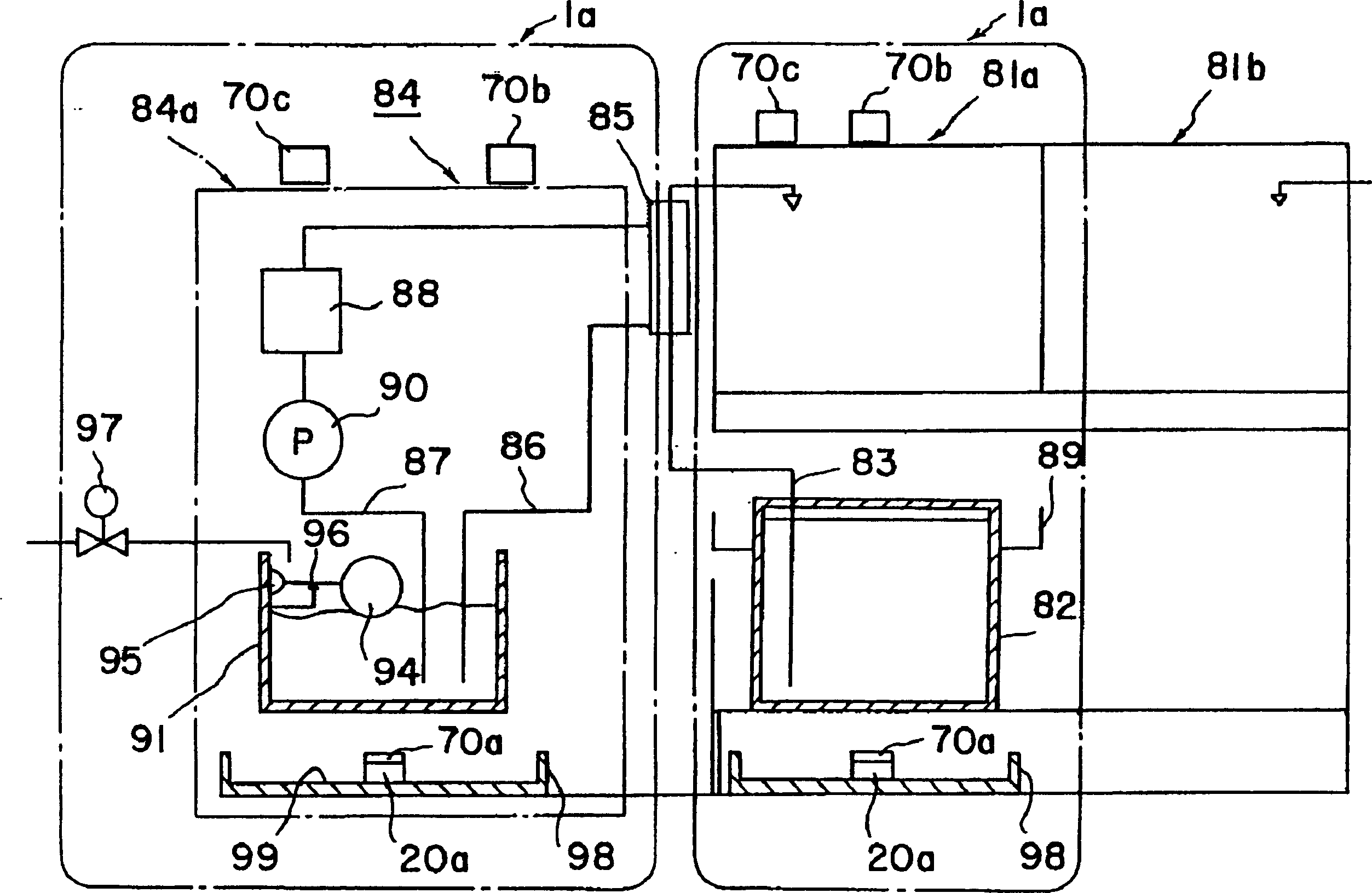
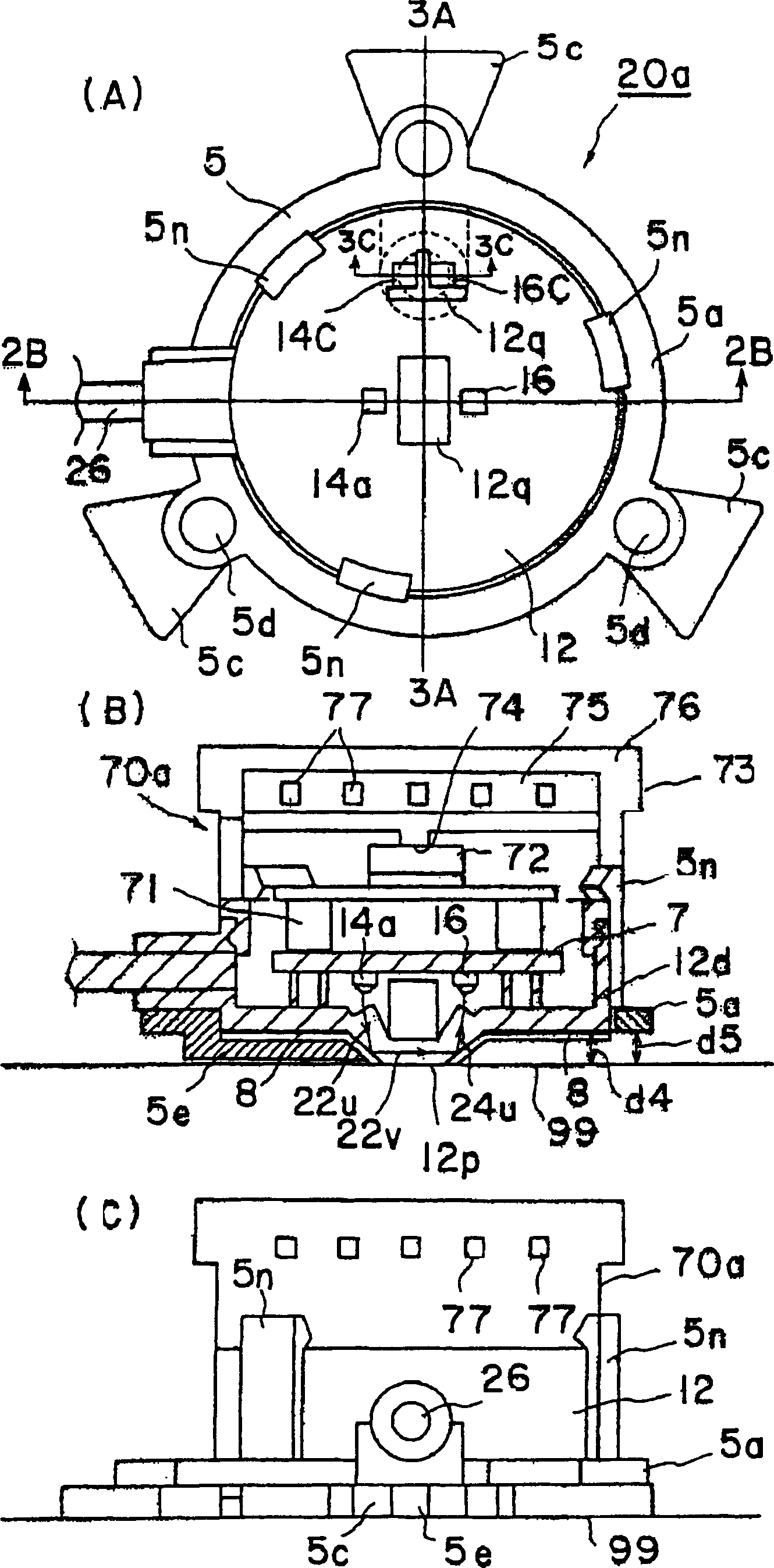
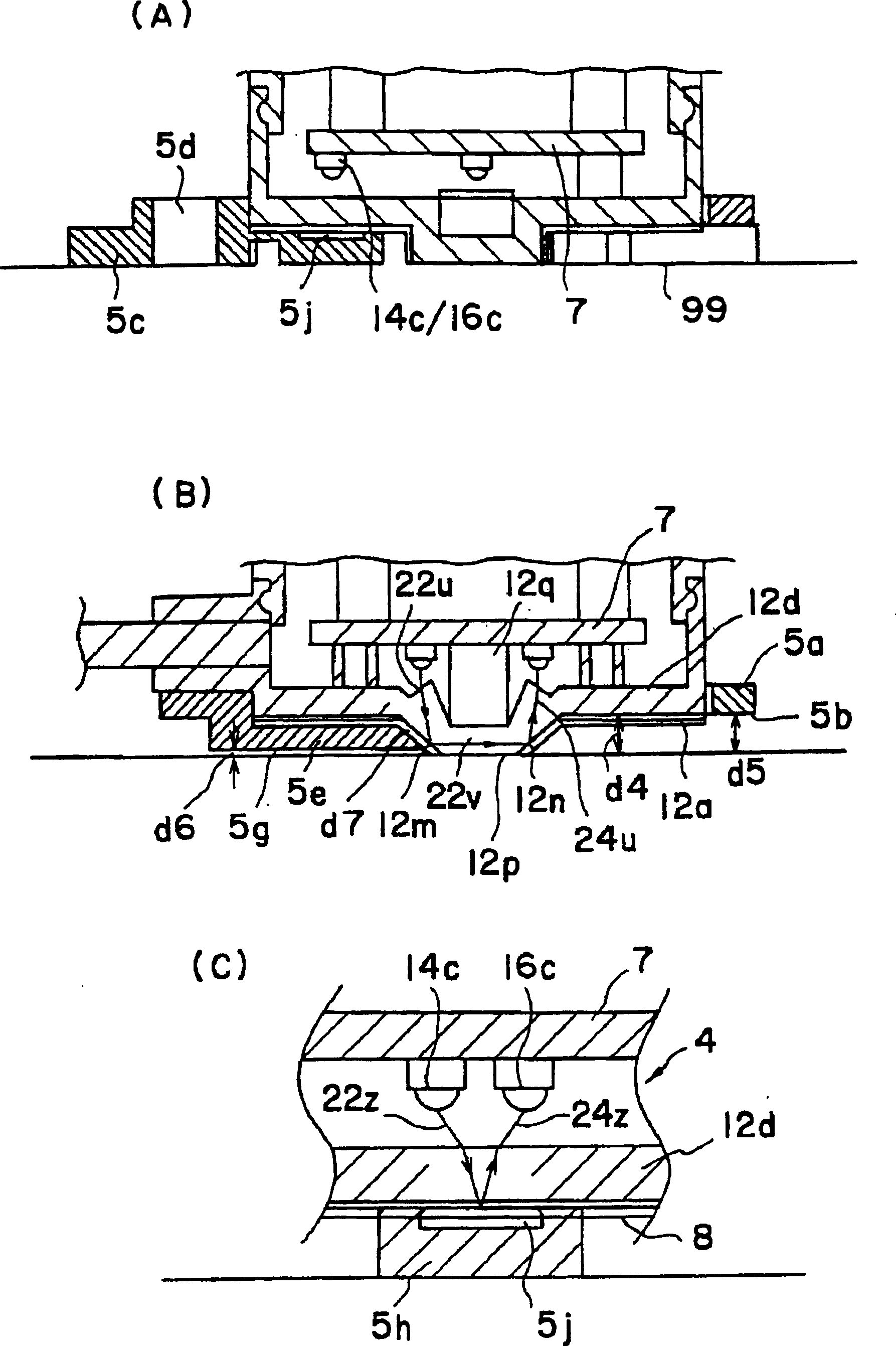
[0067] first, figure 1 It is an example of the liquid leakage detection system 1a which comprises the liquid leakage detection part (liquid leakage sensor) 20a of this invention by integrally forming the liquid leakage sensor part 20a and the alarm member 70a which includes the sounding part 72. is constructed using at least one leak sensor (in figure 1 However, on the same bottom surface and base surface with a large area, a plurality of liquid leakage sensors can also be dispersedly installed in multiple positions) as an example of the liquid leakage detection system 1a, the liquid leakage sensor has at least one The liquid leakage detection part in contact with the leakage liquid through the gas layer permeable to the leaka...

Embodiment 2

[0126] Second, with Figure 1 to Figure 6 Correspondingly expressed Figure 7 to Figure 9 Another embodiment of the liquid leakage detection system 1b and 1c is shown in which the liquid leakage detection part (liquid leakage sensor part) of the present invention is separated into a liquid leakage sensor main body 20b and an alarm part 70b including a sounding part. Numbered devices perform the same function, and, in Figure 7 In the liquid leakage detection system 1b, the liquid leakage sensor 20b and the alarm part 70b provided separately constitute an explosion-proof type liquid leakage detection system 1b through wireless signal relay. In addition, in the liquid leakage detection system 1c, the liquid leakage sensor 20b and The alarm unit 70b provided separately constitutes an explosion-proof liquid leakage detection system 1c relayed by wire.


PUM


Abstract

PROBLEM TO BE SOLVED: To enable it to pinpoint easily a liquid leakage generation part, by using liquid leakage sensors arranged on the floor or at the lowest part of a system such as a liquid leakage accommodation part, when a liquid leakage abnormality occurs.

SOLUTION: The liquid leakage sensor is provided with at least one liquid leakage sensing part which can contact the leaked liquid through a gas layer or a liquid permeating layer where the leaked liquid can permeate. In a liquid leakage sensing system provided with at least one liquid leakage sensor, an alarm means which includes a sounding means within a predetermined space region is established to the installed position of the liquid leakage sensor. When the liquid leakage sensor senses a sensor abnormality, the position of the liquid leakage sensor is pinpointed by using at least the sounding means so that it can be distinguished from the other liquid leakage sensors arranged outside the predetermined space region, and thus, the sensor abnormality of the liquid leakage sensor is alarmed.

COPYRIGHT: (C)2005,JPO&NCIPI

Description

technical field [0001] The invention relates to an improvement of a liquid leakage sensor and a liquid leakage detection system. The liquid leakage sensor and the liquid leakage detection system detect conductive liquids such as water, acidic solution, and alkaline solution, as well as ultrapure water, alcohol, diluent, Leakage of insulating liquids such as gasoline and other organic solutions. Background technique [0002] [Patent Document 1] Japanese Patent Publication No. 4-70572 [0003] [Patent Document 2] JP-A-2002-350275 [0004] In current facilities such as factories, liquid is supplied through piping. However, since the pipes are provided with joints for connection in many places, there are many cases where liquid leakage occurs from the joints. Therefore, depending on the type of liquid, one must always monitor for liquid leakage. As such a current liquid leakage sensor, known are: a conductive type liquid leakage sensor that detects changes in impedance betwe...

Claims


Application Information

Patent Timeline
IPC IPC(8): G01N21/41G01M3/00G01M3/16G01M3/38G01N27/02G08B3/10
CPCG01M3/16G01M3/38G01N27/06G01N2291/022G08B21/18G08B25/10
Inventor 林田建一岛井太小俣洋平
Owner 通电株式会社
Why Eureka
Try Eureka