Frequency circuit, radio frequency receiver and radio receiving-transmitting machine

一种射频接收机、射频收发机的技术,应用在变频电路、射频接收机及射频收发机领域,能够解决不能正常地解调等问题,达到良好选择性和灵敏度、容易安装、减小容量的效果

Inactive Publication Date: 2005-05-04
SHARP KK
View PDF2 Cites 39 Cited by
  • Summary
  • Abstract
  • Description
  • Claims
  • Application Information

AI Technical Summary

Problems solved by technology

If the 0° and 90° local oscillator signals are subjected to second-stage down-conversion as they are, the voltage vector when taken out as the baseband is rotated to the right (rotation direction from Q (90°) to I (0°)) , cannot normally demodulate

Method used


Image

  • Frequency circuit, radio frequency receiver and radio receiving-transmitting machine
  • Frequency circuit, radio frequency receiver and radio receiving-transmitting machine
  • Frequency circuit, radio frequency receiver and radio receiving-transmitting machine

Examples


Embodiment Construction

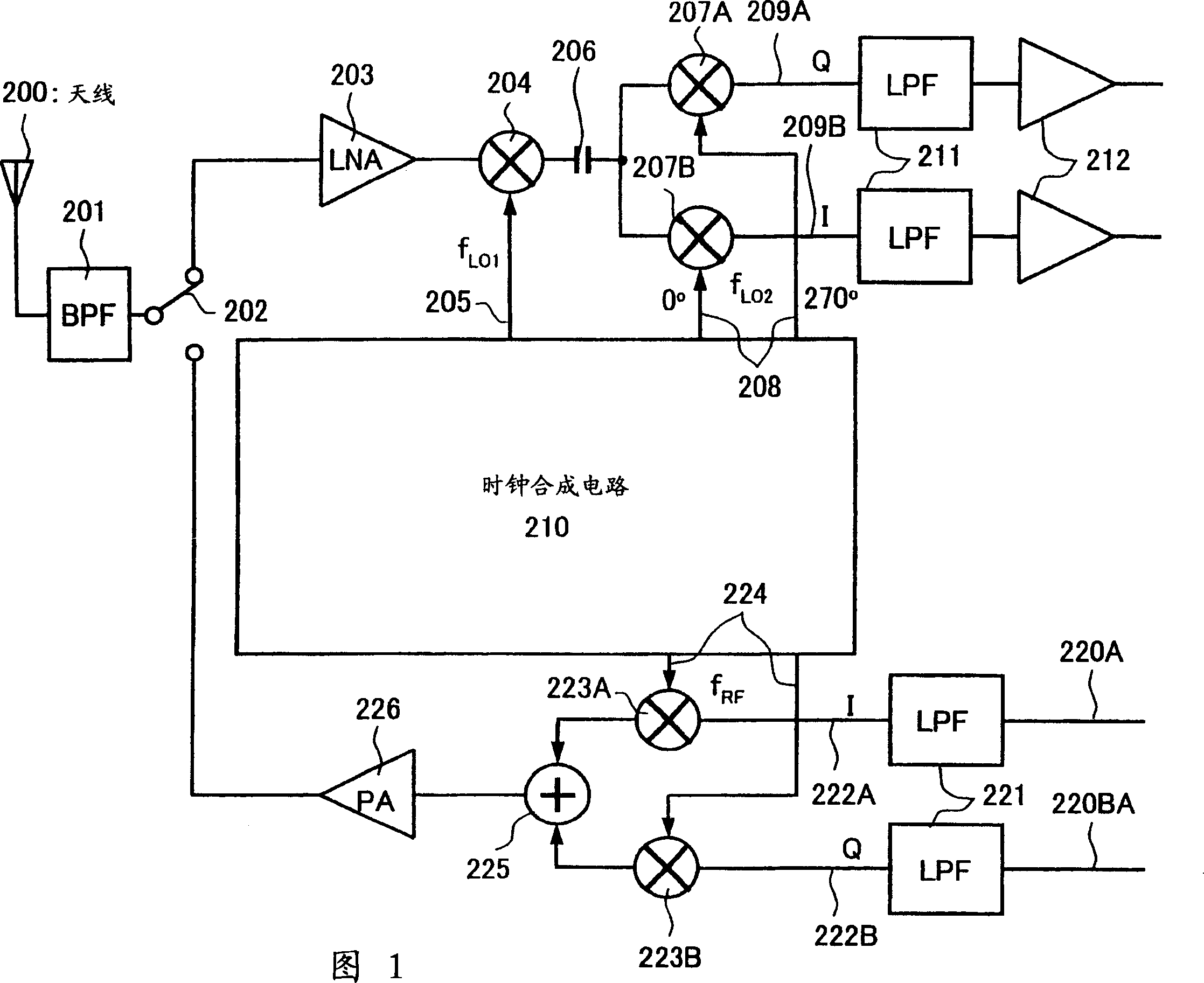
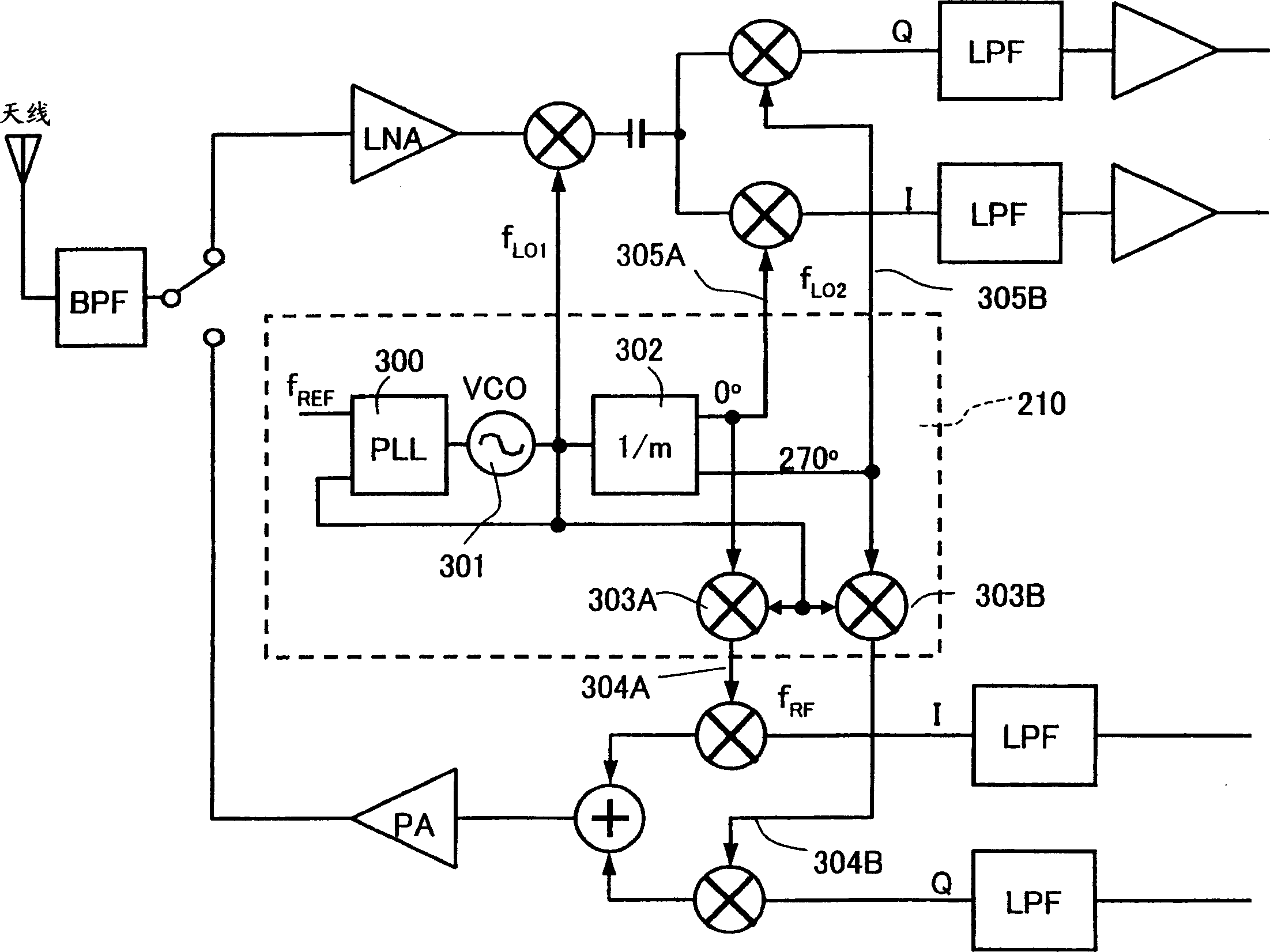
[0087] The present invention relates to an analog signal processing part of an IC transceiver (radio frequency transceiver) used in a radio frequency wireless communication system greater than or equal to 1 GHz. This wireless communication system is applicable to mobile communication systems such as mobile phones and PHSs, wireless LAN communication systems specified in the IEEE802.11 standard, and the like.

[0088] In the transceiver of the preferred mode for carrying out the present invention, the baseband signal is modulated (transmitted) and demodulated (received) by radio frequency, but there are special features in the method. That is, the present invention aims at housing the functions of the above-mentioned transceiver on an IC chip and mounting it on a portable device, thereby achieving miniaturization of the transceiver.

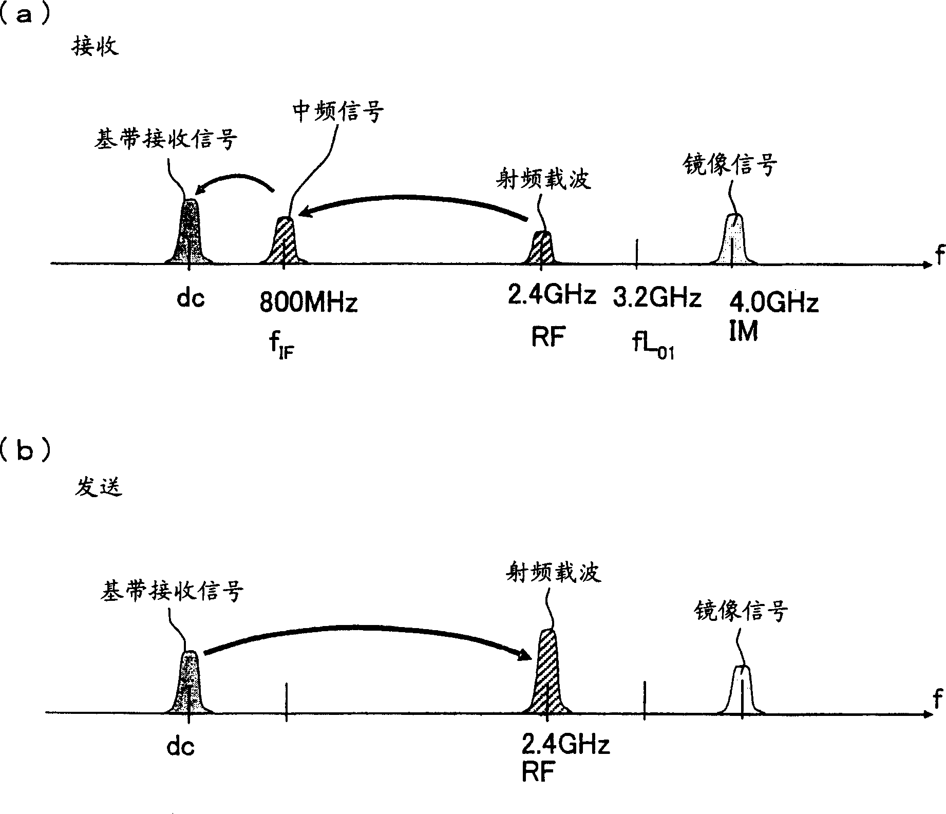
[0089] In the receiving unit of the transceiver of a preferred embodiment, two-stage frequency conversion is performed.

[0090] That is, the ra...


PUM


Abstract

A frequency conversion circuit of the present invention includes: (i) a first mixer for mixing the radio frequency signal having a frequency fRF with a first oscillation signal having a frequency fLO1 so that the radio frequency signal is downconverted into an intermediate frequency signal; and (ii) a second mixer for mixing the intermediate frequency signal sent from the first mixer with two local oscillation signals so that the intermediate frequency signal is downconverted into two base-band signals having different phases. The second local oscillation signals have phases of 0° and 270°, respectively. These frequencies satisfies: <?in-line-formulae description="In-line Formulae" end="lead"?>fLO1=kxfRF(k>1) <?in-line-formulae description="In-line Formulae" end="tail"?> <?in-line-formulae description="In-line Formulae" end="lead"?>fLO2=fLO1 / m, (m>1)<?in-line-formulae description="In-line Formulae" end="tail"?> <?in-line-formulae description="In-line Formulae" end="lead"?>k=m / (m-1).<?in-line-formulae description="In-line Formulae" end="tail"?> This arrangement ensures (i) a small frequency conversion circuit that can be mounted on an integrated circuit, (ii) a radio frequency receiver including the frequency conversion circuit, and (iii) a radio frequency transceiver including the radio frequency receiver.

Description

technical field [0001] The present invention relates to a radio frequency (RF) receiver and a radio frequency transceiver, and a frequency conversion circuit applicable to them, applicable to a wireless data communication system that can extract in-phase mobile phone and PHS (Personal Handyphone System; Personal Handyphone System) and other mobile communication systems, as well as wireless local area network (LAN) communication systems determined in accordance with IEEE 802.11x specifications. Background technique [0002] A typical existing RF transceiver is shown in Figure 10 . The radio frequency transceiver is composed of an antenna 1, a radio frequency preselection filter (bandpass filter (BPF)) 2, a duplex switch 3, and a receive path and a transmit path. The duplex switch 3 connects the antenna 1 to the path of the receiver 1004 or the path of the transmitter 1005 . The purpose of the RF transceiver is to convert baseband (BB) data to RF. In terms of signal energy...

Claims


Application Information

Patent Timeline
Patent Type & Authority Applications(China)
IPC IPC(8): H03D7/00H03D7/14H03D7/18H03K9/00H04B1/16H04B1/26H04B1/40
CPCH03D7/1466H03D7/1441H04B1/408H03D7/1458H03D2200/0084H03D7/165H04B1/40
Inventor 艾伯托·O·阿丹神谷真司
Owner SHARP KK
Why Eureka
Try Eureka