Light adjustable multifocal lenses
A multi-focal lens, lens technology, applied in the direction of lenses, optics, optical components, etc., can solve the problems of adding part deviating from the visual axis of glasses and losing multi-focus.
- Summary
- Abstract
- Description
- Claims
- Application Information
AI Technical Summary
Problems solved by technology
Method used
Image
Examples
Embodiment 1
[0065] A 6 mm diameter intraocular lens containing a silicone based MC was fabricated using standard molding techniques known to those skilled in the art. The lens comprises a first polymer precursor prepared from silane crosslinked vinyl terminated diphenylsiloxane dimethylsiloxane. The first polymer precursor constitutes approximately 70% by weight of the lens composition. The lens also included about 30 wt% of MC (methacrylate-terminated polydimethylsiloxane), 1 wt% (based on MC) of a photoinitiator (benzoin-tetrasiloxane-benzoin) and 0.04 wt% (based on MC) UV absorber. The starting nominal power of this lens is 30 diopters. The center of the lens was then irradiated with 365 nm light for 60 seconds, the intensity profile of which was represented by the following equation:
[0066] I = I 0 e ( r - r ...
Embodiment 2
[0074] A unique aspect of the above technique is the ability to first vary the power of the IOL over most of its aperture and then illuminate a small area of the lens (0-3 mm) to form a bifocal lens as described in Example 1. The advantage of this embodiment is to first implant the optically adjustable lens into the patient, wait for the required healing time for the refractive properties of the eye to stabilize (typically 2-4 weeks), measure the refractive index of the patient's eye to determine the necessary Correction, if correction is required, to normalize the patient, irradiates the lens to change the power of the lens over most stops, then reirradiates a smaller area (1.5-3 mm) of the lens along the visual axis of the patient's eye to provide Multifocals necessary for near and far vision.
[0075] An example of this is Molding + 20.0D LAL comprising 75wt% silicone matrix, 25wt% MC, 0.83wt% PI and 0.04wt% UV absorber. First use an average intensity of 10mW / cm 2 The l...
Embodiment 3
[0078] In the past, clinical use of bifocal or multifocal IOLs has been met with some resistance from patients due to the loss of contrast sensitivity and flare inherent in this type of lens design. In the past, the only way for physicians to reverse the adverse effects of a previously implanted multifocal or bifocal IOL was to remove the IOL and reimplant a standard monofocal IOL. However, the optically tunable lens technology disclosed here and previously published in Calhoun Vision provides a way to reverse the multifocality of the LAL, effectively restoring it to a monofocal condition. This allows for reversal without surgical removal, with distinct advantages.
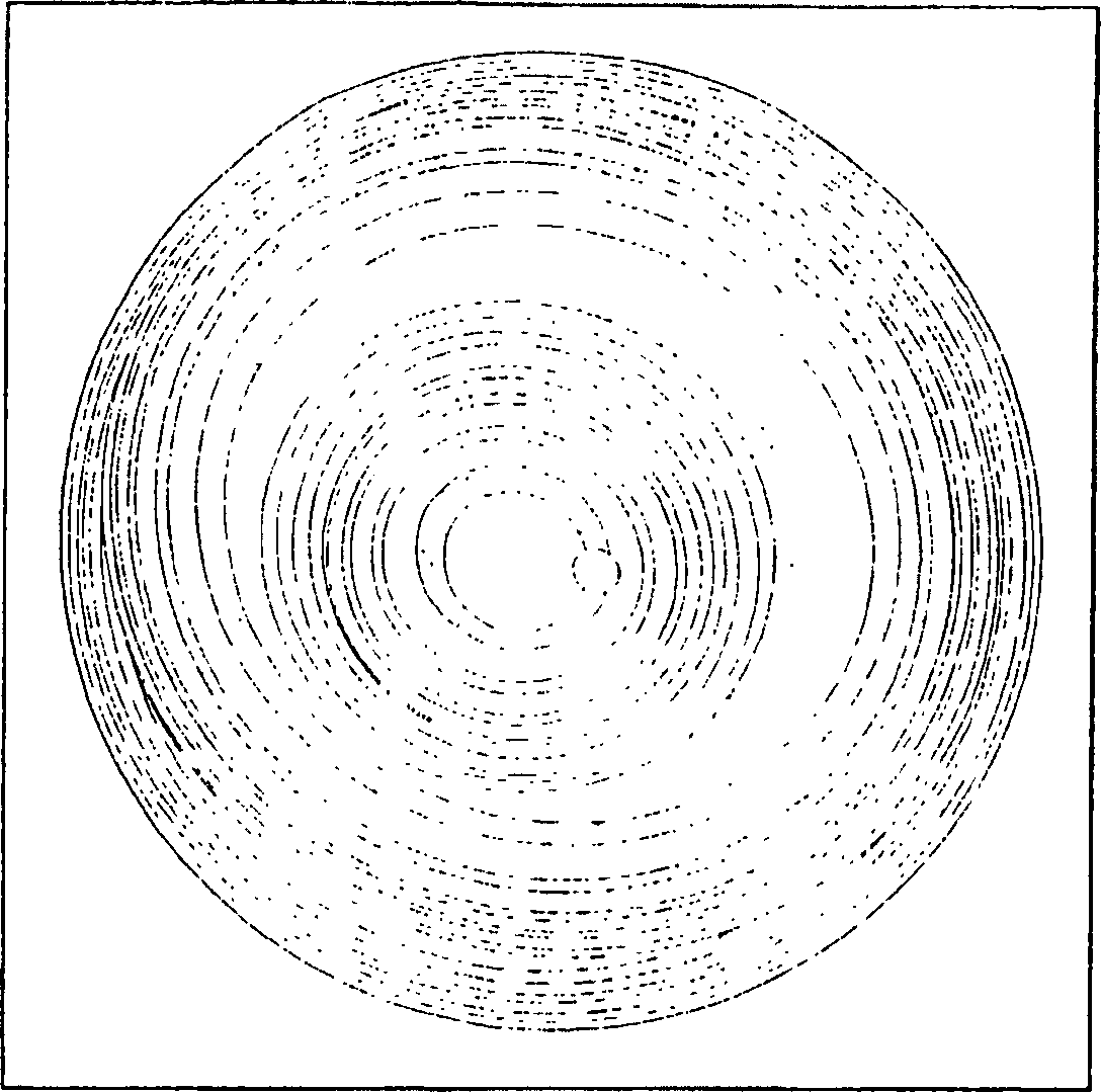
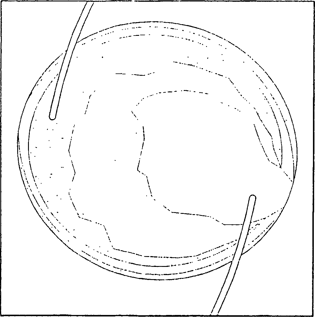
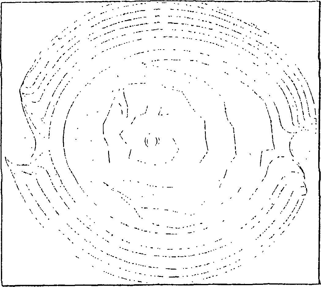
[0079] As an example of this method, a +20.0D LAL comprising 75wt% silicone precursor, 25wt% MC, 0.83wt% PI and 0.04wt% UV absorber was molded. The pre-irradiated Fizeau interference fringes are shown in Figure 4A middle. Then use an intensity of 6mW / cm 2 The light was continuously irradiated to LAL twice, ea...
PUM
 Abstract
Description
Claims
Application Information
 - R&D
- Intellectual Property
- Life Sciences
- Materials
- Tech Scout
- Unparalleled Data Quality
- Higher Quality Content
- 60% Fewer Hallucinations
Browse by: Latest US Patents, China's latest patents, Technical Efficacy Thesaurus, Application Domain, Technology Topic, Popular Technical Reports.
© 2025 PatSnap. All rights reserved.Legal|Privacy policy|Modern Slavery Act Transparency Statement|Sitemap|About US| Contact US: help@patsnap.com


