Residual current circuit breaker

A leakage circuit breaker and circuit technology, applied in circuit devices, emergency protection circuit devices, electrical components, etc., can solve the problems of larger test circuit installation space, larger test circuit installation space, and larger contact application, and achieve accurate And stable working test, accurate and stable leakage test, the effect of reducing the burden voltage

Inactive Publication Date: 2005-06-01
FUJI ELECTRIC FA COMPONENTS & SYST CO LTD
View PDF1 Cites 31 Cited by
  • Summary
  • Abstract
  • Description
  • Claims
  • Application Information

AI Technical Summary

Problems solved by technology

[0009] However, in such a conventional device, since it is necessary to set the number of current-limiting resistance elements and selection switches corresponding to the type of rated voltage used, the installation space of the test circuit increases and the number of parts decreases. increase, there is a problem that the manufacturing cost increases
[0010] Moreover, especially when the rated voltage is high, a large voltage is often applied between the contacts when the test switch is turned on, so it is necessary to increase the contact interval of the test switch to improve the withstand voltage, so there is still the problem of increasing the size of the switch.
[0011] In an earth leakage circuit breaker having such a latter test circuit, when the rat...

Method used


Image

  • Residual current circuit breaker
  • Residual current circuit breaker
  • Residual current circuit breaker

Examples


Embodiment 1

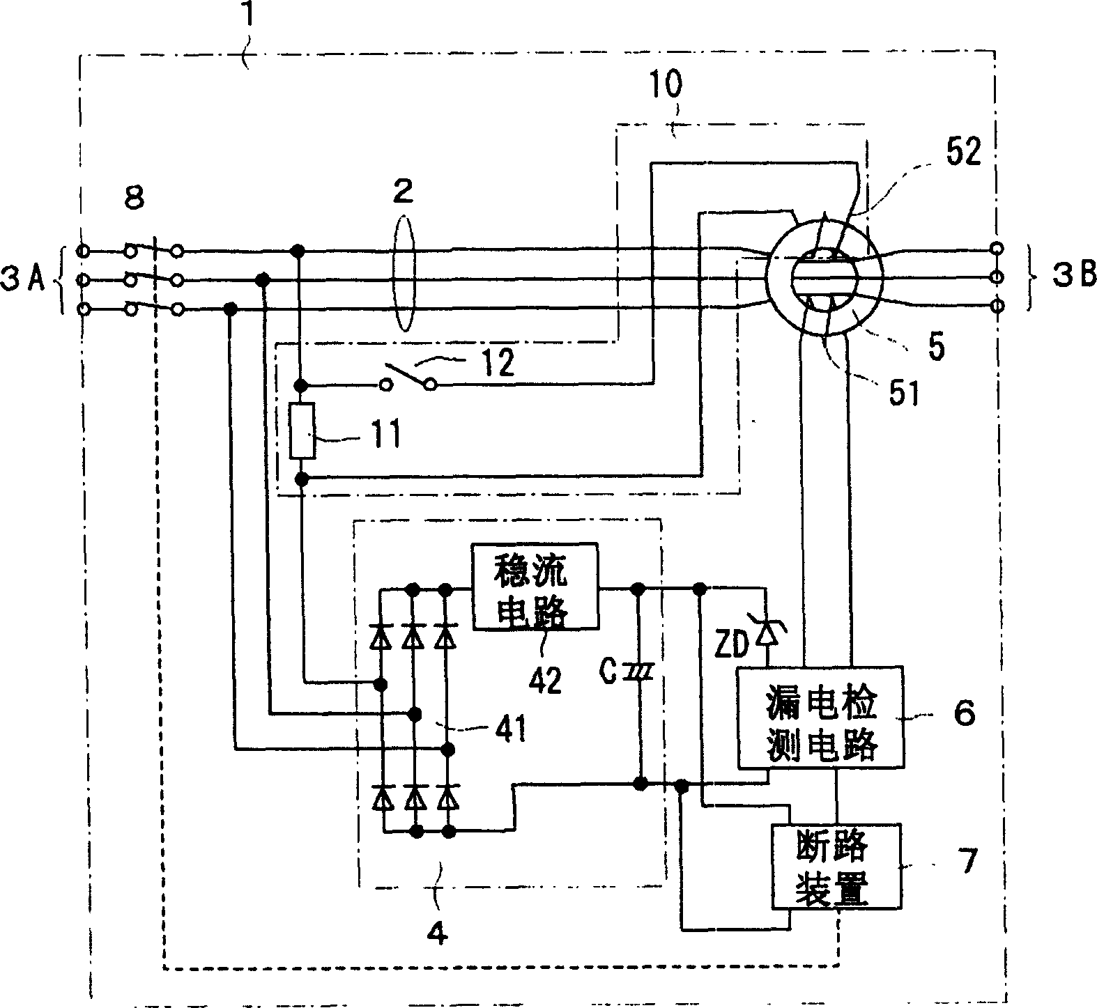
[0031] figure 1 It is a configuration diagram showing Embodiment 1 of the present invention.

[0032] exist figure 1 Among them, 1 is an earth leakage circuit breaker, and usually all structural elements are accommodated in a molded case made of insulating resin, and are compactly formed. This leakage circuit breaker 1 is equipped with: the main circuit 2 that connects the power supply side connection terminal 3A and the load side connection terminal 3B; Flow through the zero-phase current converter 5 of the leakage current of the main circuit; monitor the detection current of the leakage detection coil 51 of the zero-phase current converter 5, and judge the leakage detection circuit 6 with or without leakage; according to the leakage detection circuit 6 An output signal indicating leakage, a circuit breaker 7 for breaking the on-off mechanism of the switch part 8 to open the switch part; and a power supply circuit 4 for supplying operating power to the leakage detection c...

Embodiment 2

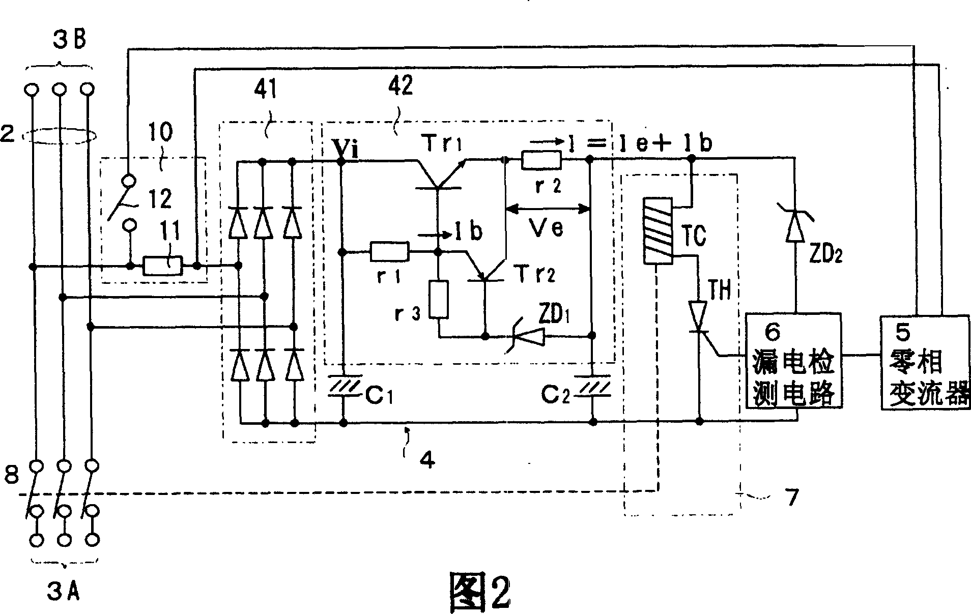
[0044] Secondly, Figure 4 The structure of Embodiment 2 of the present invention is shown in .

[0045] The difference between Embodiment 2 and Embodiment 1 lies in the input resistance R 1 , R 2 and R 3 Other configurations of the phases connected to the AC input side of the rectifier circuit 41 of the power supply circuit 4 are the same.

[0046] Thus, if the input resistor R 1 , R 2 , R 3 connected to the power circuit 4, these resistance elements and the smoothing capacitor C in the power circuit 4 can be used 1 (Refer to FIG. 2 ) Since a filter circuit is formed, a high-frequency surge voltage can be absorbed, so that the surge voltage withstand capacity of the power supply circuit 4 and the test switch 12 of the test circuit 10 can be improved.

Embodiment 3

[0048] Figure 5 It is a configuration diagram showing Embodiment 3 of the present invention.

[0049] Should Figure 5 The shown embodiment 3 is to combine two Zener diodes ZD 3 and ZD 4 An embodiment in which the two ends of the test resistance element 11 are connected in reverse series to limit the terminal voltage of the test resistance element 11 below a certain voltage determined by the Zener diode. Even if the resistance value of the test resistance element 11 is not reduced, the voltage at both ends can be limited below a certain value by setting the Zener diode, and the burden of the AC voltage of the test switch 12 can be reduced, so the contact points can be separated. Narrower, enabling overall miniaturization of the switch.


PUM


Abstract

The invention discloses a leakage circuit breaker which has a simple and small structure of a test circuit and can simultaneously perform accurate leakage tests. As a power supply circuit for supplying power to the leakage detection circuit in the leakage circuit breaker, a power supply circuit with a constant current circuit that converts the AC current supplied from the main circuit into a DC current and supplies a constant DC current to the leakage detection circuit is used, and the test resistance The elements are arranged in series in the circuit connecting the main circuit and the AC input end of the current stabilizing circuit, and the test coil of the zero-phase converter is connected to both ends of the resistance element through a test switch to form a leakage test circuit.

Description

technical field [0001] The present invention relates to an earth leakage circuit breaker for detecting electric leakage occurring in a power distribution system connected to motors and various other loads to prevent contagious accidents, and in particular to an improvement of the test circuit. Background technique [0002] In order to accurately test the operation of the earth leakage circuit breaker, various efforts have been made on the leakage test circuit of the earth leakage circuit breaker. One example thereof is shown in Patent Document 1. Figure 7 The structure of the earth leakage circuit breaker shown in this patent document 1 is shown in . [0003] Figure 7 The earth leakage circuit breaker has multiple rated voltages, for example, there are three rated voltages of 100, 200 and 400V. The leakage circuit breaker 1 shown in the figure has a power supply side connection terminal 3A and a load side connection terminal 3B, and in the main circuit connected between t...

Claims


Application Information

Patent Timeline
IPC IPC(8): H01H83/02H01H83/04H02H1/06H02H3/33
CPCH02H1/06H02H3/335H01H83/04
Inventor 辻伸彦浅野久伸
Owner FUJI ELECTRIC FA COMPONENTS & SYST CO LTD
Why Eureka
Try Eureka