
Optical spectral power monitors employing time-division-multiplexing detection schemes

An optical detector and spectrum technology, applied in the field of spectrum monitors and analyzers, achieves the effects of simple cost, great versatility, and improved accuracy

Inactive Publication Date: 2005-06-01
CAPELLA PHOTONICS INC
View PDF0 Cites 14 Cited by
  • Summary
  • Abstract
  • Description
  • Claims
  • Application Information

AI Technical Summary

Problems solved by technology

This polarization sensitivity can be particularly severe for highly dispersive diffraction gratings (e.g., holographic gratings) needed to provide enhanced spectral resolution in spectral power monitors

Method used


Image

  • Optical spectral power monitors employing time-division-multiplexing detection schemes
  • Optical spectral power monitors employing time-division-multiplexing detection schemes
  • Optical spectral power monitors employing time-division-multiplexing detection schemes

Examples


Embodiment Construction

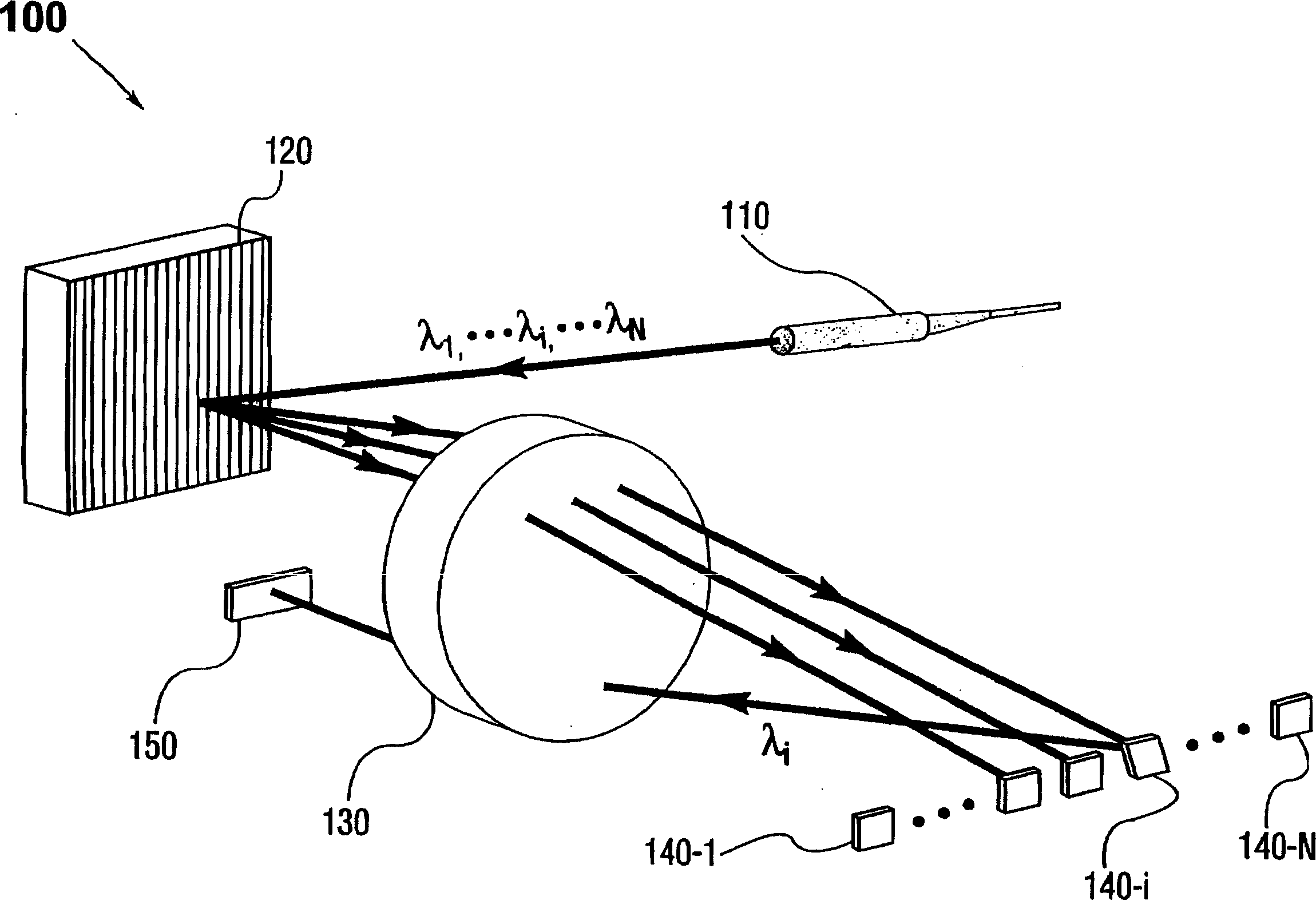
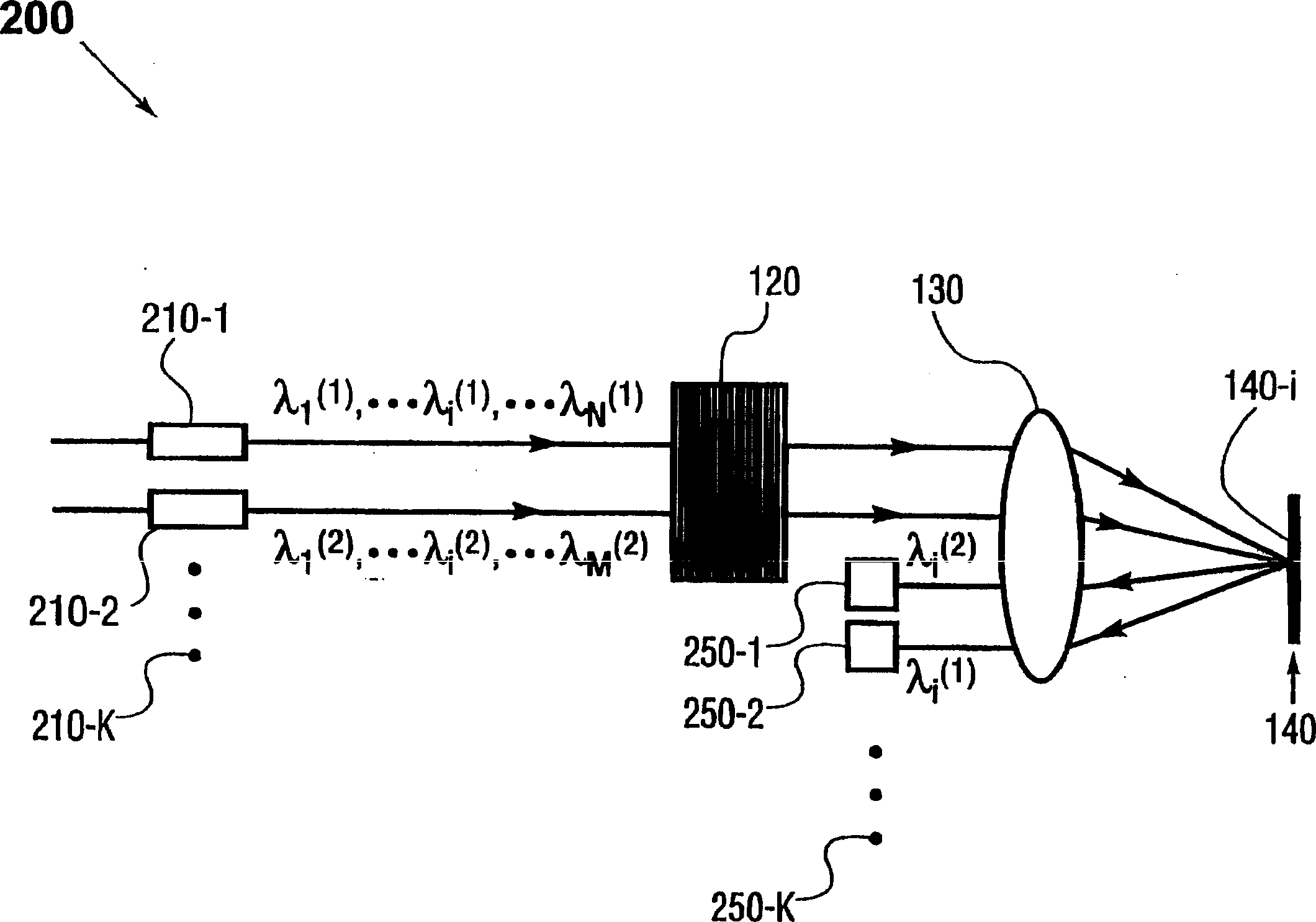
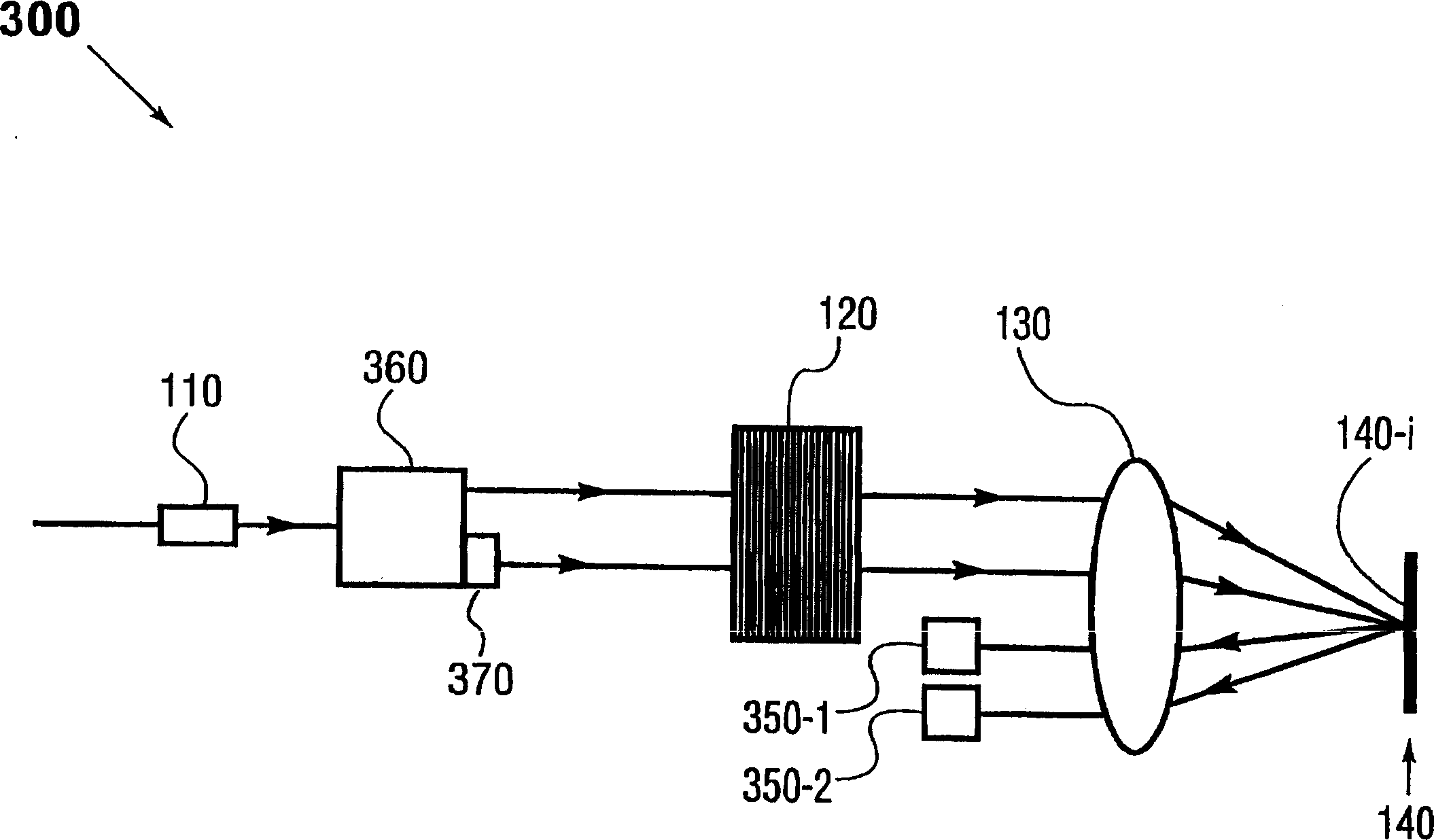
[0022] figure 1 A perspective view showing a first embodiment of a spectrum monitoring device according to the present invention. To illustrate the general principle of the present invention, the spectral power monitoring device 100 includes: an input port 110, which may be a fiber collimator; a wavelength disperser 120, one form of which may be a diffraction grating; and a beam focuser 130, which may be a focusing Lens; and a beam steering element array 140, one form of which may be micromirrors 140-1 to 140-N. The spectral power monitoring device 100 may further include an optical detector 150, which may be a photodiode combined with an associated detection circuit.

[0023] For the purpose of illustration and clarity, only a few (for example, three) selected spectral channels and the input multi-wavelength optical signal are shown in the figure figure 1 And the following figure. However, it should be noted that there can be any number of spectral channels in the spectral pow...


PUM


Abstract

A method and apparatus for spectral power monitoring using a time division multiplexing detection scheme. The device uses a wavelength disperser (120), such as a diffraction grating, to split an optical signal into a plurality of spectral channels, and an array (140) of beam manipulation elements is positioned to correspond to the spectral channels. The beam steering elements are individually controllable to direct the spectral channels into an optical detector (150) in a time-division multiplexed sequence. The device further employs a polarization diversity scheme for polarization insensitive operation. This enhances the spectral resolution of the device while providing increased accuracy in spectral power detection. Spectral power monitors constructed in accordance with the present disclosure are well suited for WDM optical network connection applications.

Description

[0001] inventor [0002] Pavel Polykin, Mark H. Garrett and Jeffrey P. Wilde Technical field [0003] The present invention generally relates to spectrum monitors and analyzers. More specifically, it relates to a new type of spectrum monitor adopting a time division multiplexing detection scheme, which is suitable for WDM optical networking applications. Background technique [0004] As optical communication networks using wavelength division multiplexing (WDM) become increasingly popular, there is a need for a new type of optical performance monitor, including a spectral power monitor. [0005] Conventional spectral power monitors in the art typically use wavelength dispersing devices, such as diffraction gratings or dispersing prisms, to divide the multi-wavelength optical signal into a spatial array of spectral channels with distinct central wavelengths. An array of photodetectors (such as photodiodes) are placed to individually detect spectral channels, thereby providing optic...

Claims


Application Information

Patent Timeline
Patent Type & Authority Applications(China)
IPC IPC(8): G01J3/32G02B6/34G02B6/42H04J14/00H04J14/02H04J14/08
CPCG01J3/021G01J3/0224G01J3/32G02B6/2706G02B6/2793G02B6/2931G02B6/29311G02B6/29397G02B6/4249G02B6/425H04J14/02H04J14/08
Inventor P·波林金J·P·维尔德M·H·加雷特
Owner CAPELLA PHOTONICS INC
Learn More