Extracting device
A technology of extractor and distributor, which is applied in the direction of liquid solution solvent extraction, etc., can solve the problems of disc extraction tower height, small processing capacity of centrifugal extractor, large energy consumption, etc., and achieve the reduction of extractor size and extraction efficiency The effect of improving and reducing energy consumption
- Summary
- Abstract
- Description
- Claims
- Application Information
AI Technical Summary
Problems solved by technology
Method used
Image
Examples
Embodiment 1
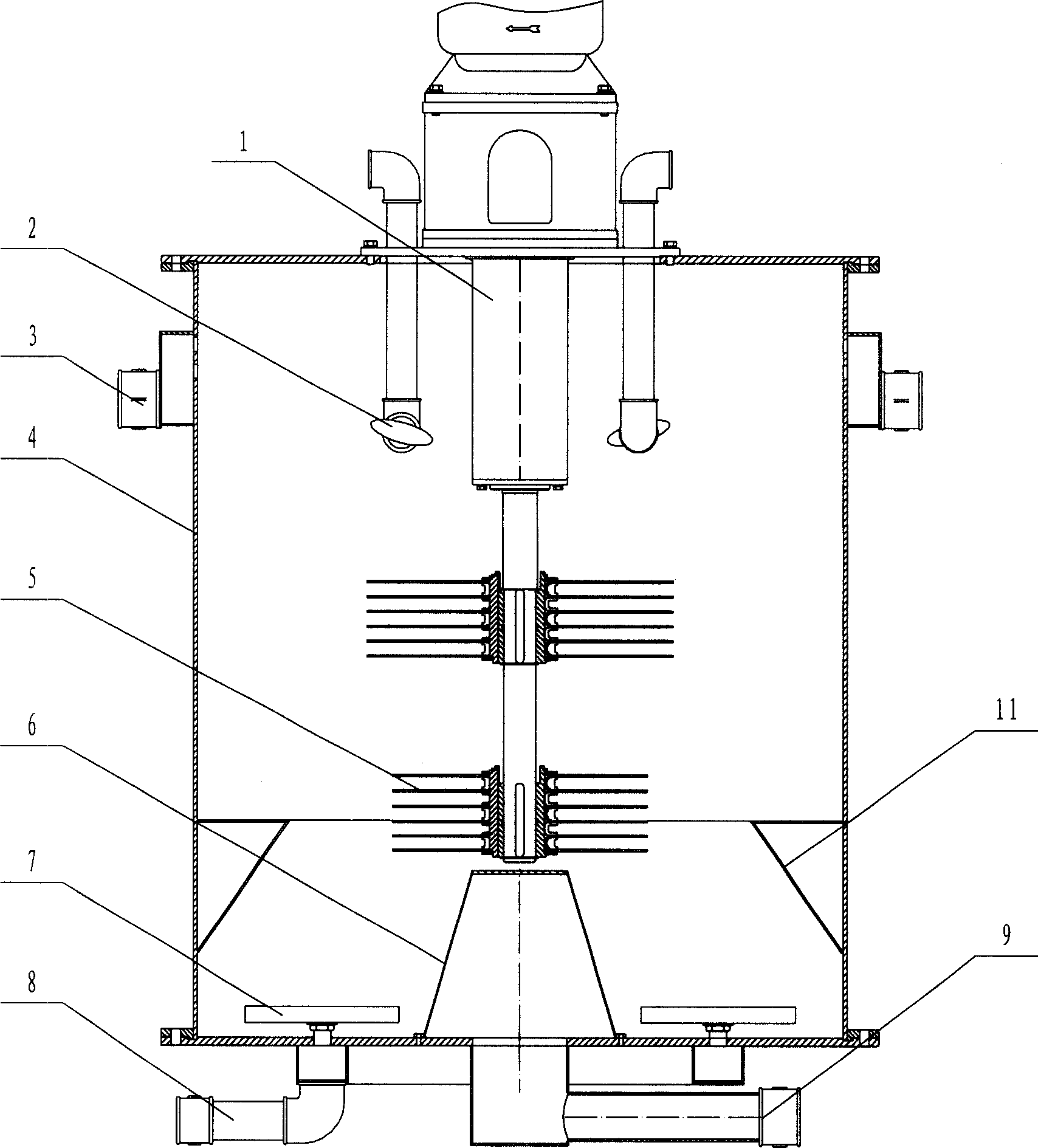
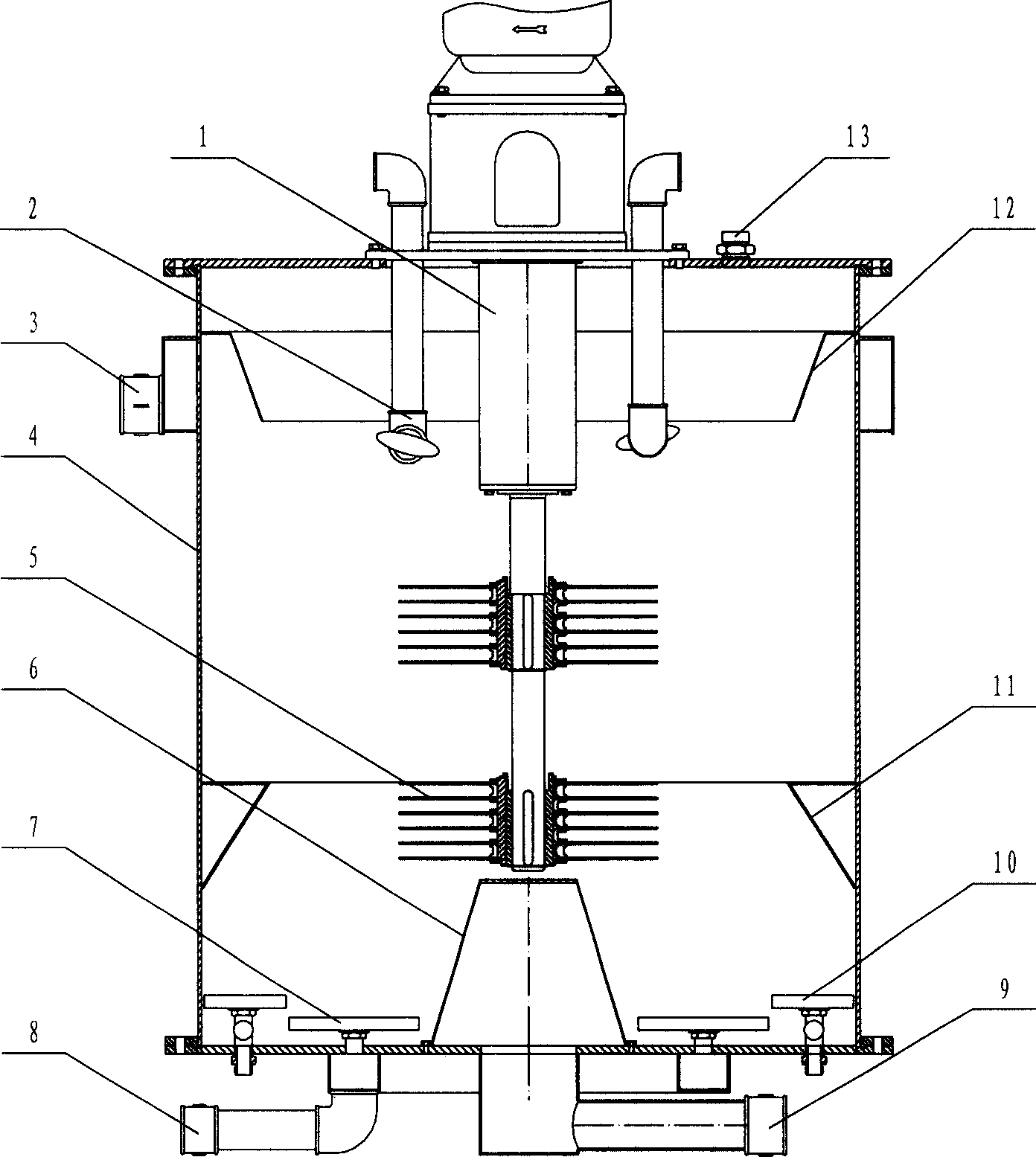
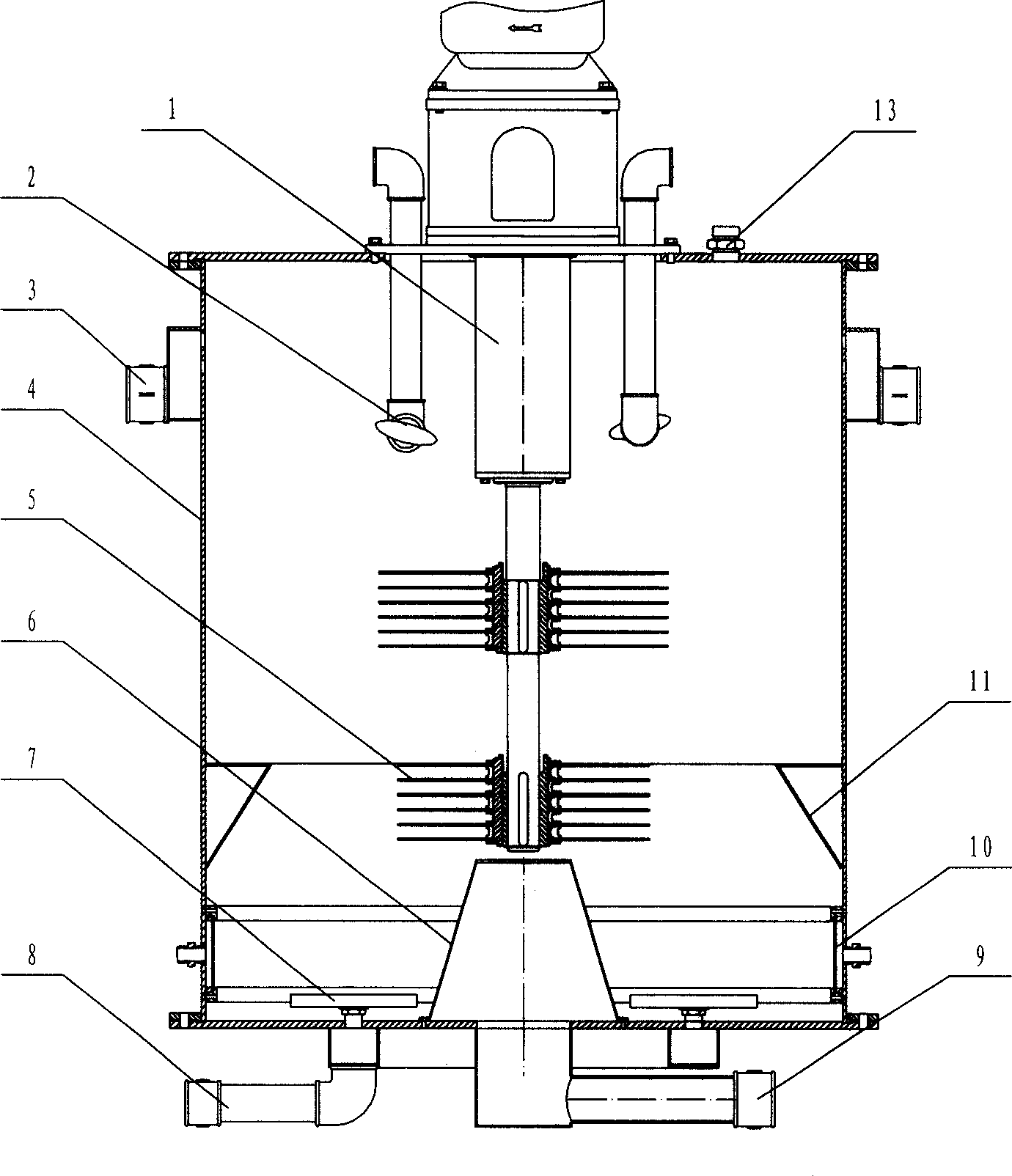
[0074] See figure 1 , Is an extractor designed according to the first technical scheme of the present invention. It includes a vertical cyclone chamber 4, a set of transmission device 1, two sets of pin wheels 5, a frustum-shaped heavy phase liquid distributor 6, a set of disc type light phase liquid distribution device 7, two sets of light phase liquid skimming器2, a rectifier cone 11.
[0075] The transmission device 1 is located in the upper part of the cyclone chamber 4. The heavy phase liquid distributor 6 and the light phase liquid distribution device 7 are both in the lower part of the cyclone chamber 4, the heavy phase liquid distributor 6 is in the center, the light phase liquid distribution device 7 is on the periphery, and the pin wheel 5 is located above the heavy phase liquid distributor 6. The light phase skimmer is above the pin wheel 5.
[0076] The pin wheel 5 is arranged radially and evenly densely by U-shaped needles and hung on a positioning ring. The positioni...
Embodiment 2
[0088] See Figure 6 , Is a high-speed centrifugal extractor designed according to the second technical scheme of the present invention. It includes a shell 16 composed of a cylinder, a spacer ring and a flange, a set of upper transmission device 1, two sets of tandem pin wheels 5 rotors, a lower trumpet-shaped centrifuge tube 17 with steps, and a set of ring plates. Light phase liquid distribution device 7, a set of intersecting liquid inlet components, and a transmission fixing seat 20.
[0089] The upper part of the side wall of the shell 16 has an eccentrically intersecting light-phase liquid outlet 18 joint, and the middle part has at least two orthogonal heavy-phase liquid outlet 3 joints for respectively taking heavy phases of different purity, and a solid phase outlet 15 joint at the lower part.
[0090] The outer wall of the centrifugal cylinder 17 has a mating surface with the spacer ring and the connecting flange. The lower part of the inner wall is tapered, mainly focu...
PUM
 Abstract
Description
Claims
Application Information
 - R&D
- Intellectual Property
- Life Sciences
- Materials
- Tech Scout
- Unparalleled Data Quality
- Higher Quality Content
- 60% Fewer Hallucinations
Browse by: Latest US Patents, China's latest patents, Technical Efficacy Thesaurus, Application Domain, Technology Topic, Popular Technical Reports.
© 2025 PatSnap. All rights reserved.Legal|Privacy policy|Modern Slavery Act Transparency Statement|Sitemap|About US| Contact US: help@patsnap.com


