Petrol engine variable valve timing device

A gasoline engine and gas timing technology, which is applied in the direction of engine components, machines/engines, mechanical equipment, etc., can solve the problems of complex structure, high cost, and difficulty in popularization, and achieve the effect of simple structure and low cost

Inactive Publication Date: 2005-06-29
CHONGQING ZONGSHEN ENGINE MFG
View PDF0 Cites 18 Cited by
  • Summary
  • Abstract
  • Description
  • Claims
  • Application Information

AI Technical Summary

Problems solved by technology

[0005] Now the variable valve phase mechanism that is used more often is mainly realized by the electronically controlled hydraulic mechanism to realize the change of the valve phase, which is mainly controlled and executed by the information acquisition system, that is, several speed, oil pressure, temperature sensors, and the

Method used


Image

  • Petrol engine variable valve timing device
  • Petrol engine variable valve timing device
  • Petrol engine variable valve timing device

Examples


Embodiment 1

[0017] Such as figure 2 As shown, it is a partial cross-sectional schematic diagram of the structure of the gasoline engine variable valve timing mechanism according to Embodiment 1 of the present invention. From figure 2 It can be seen from the above that the present invention provides a variable valve timing mechanism for a gasoline engine, which includes a camshaft 31 on which a plurality of cams 1 and 3 are arranged, and the camshaft 31 is also provided with driven cams in sequence. Disc 2 and driving wheel 4, driven disc 2 is provided with boss 21, and driving wheel 4 is provided with arc-shaped groove 42 correspondingly, and this boss 21 inserts arc-shaped groove 42 and can slide in arc-shaped groove 42, makes The driven disc 2 can generate displacement relative to the driving wheel 4 .

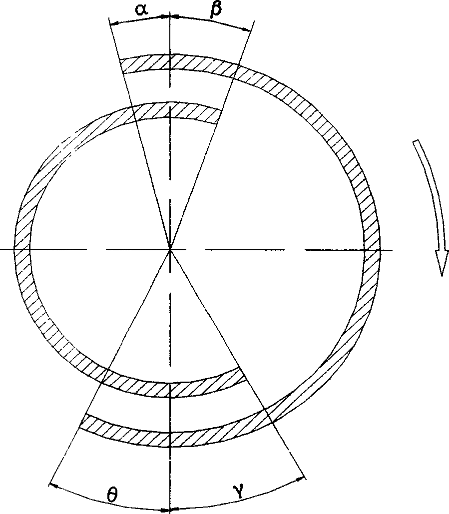
[0018] 4 and 5 are schematic diagrams of the moving positions of the centrifugal blocks when the engine of the present invention operates at low speed and high speed, respectively. ...

Embodiment 2

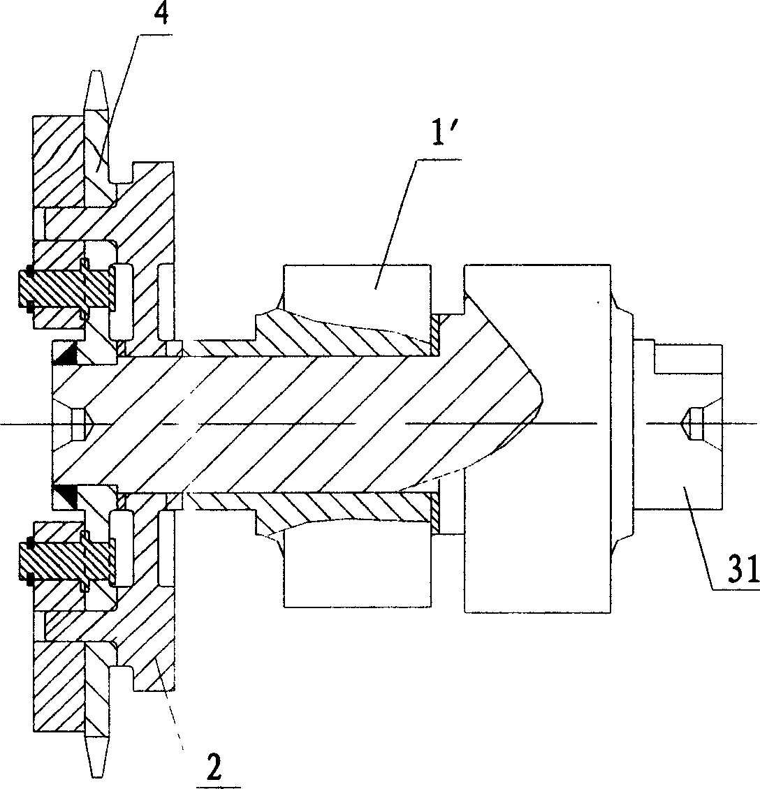
[0022] Such as image 3 As shown, it is a partial cross-sectional schematic diagram of the structure of the gasoline engine variable valve timing mechanism according to the second embodiment of the present invention. From image 3As can be seen in the figure, the cam can also be a free cam 1' sleeved on the camshaft 31, so that the free cam 1' rotates relative to the drive wheel 4. In order to connect stably, the contact surface of driven disc 2 and free cam 1' is a claw type connection. The difference between this embodiment and the first embodiment is that the end of the camshaft 31 and the drive wheel 4 are connected together by welding, therefore, there is no need to install the parts used in the first embodiment to prevent the axial direction of the parts. Movement limit device.

[0023] Other technical features of this embodiment are the same as those of Embodiment 1. Please refer to Embodiment 1 for specific technical solutions, and details are not repeated here.


PUM


Abstract

A gasoline engine variable valve timing mechanism, which includes a camshaft, the camshaft is provided with a plurality of cams, the camshaft is also provided with a driven disc and a driving wheel in sequence, and the driven disc is provided with a cam Correspondingly, there is an arc-shaped groove on the drive wheel, and the convex column is inserted into the arc-shaped groove and can slide in the arc-shaped groove, so that the driven plate can be displaced relative to the drive wheel; two centrifugal blocks are arranged on the outside of the drive wheel , the centrifugal block is a sheet-shaped body, and its edge contour is an irregular curve. The positioning hole is set on the centrifugal block, which is correspondingly set on the fixed column of the driving wheel. The two ends of the two centrifugal blocks are respectively connected end to end by elastic elements. A sliding groove is provided on the block, and the boss on the driven plate is inserted into the sliding groove through the driving wheel and can slide in the sliding groove. The variable valve phase mechanism provided by the present invention saves complicated and expensive components such as the existing ECU, solenoid valves and multiple sensors, and the overall mechanism has simple structure, few parts, easy processing and low cost.

Description

technical field [0001] The invention relates to a gas distribution mechanism of a gasoline engine, in particular to a variable gas distribution phase mechanism of a gasoline engine, which belongs to the technical field of gasoline engine manufacturing. Background technique [0002] Such as figure 1 Shown is the gas distribution phase diagram of an ordinary gasoline engine. From figure 1 It can be seen that α is the intake advance angle, β is the exhaust late closing angle, θ is the intake late closing angle, and γ is the exhaust advance angle. [0003] The selection of valve timing depends on the performance requirements of the engine and must be compatible with the shape and size of the engine air passage. Valve timing has a great influence on the engine's air exchange quality, pumping loss, charging efficiency, external torque characteristics, idling stability, and harmful emissions. In order to ensure that the intake valve has a large opening area and the scavenging e...

Claims


Application Information

Patent Timeline
IPC IPC(8): F01L1/06F01L1/34
Inventor 郝宁宁
Owner CHONGQING ZONGSHEN ENGINE MFG
Why Eureka
Try Eureka