Phase lock loop and loop filter therefor

A loop filter and circuit technology, which is applied in the direction of automatic power control and electrical components, can solve the problems of general products without structure and inconvenience, and achieve the effects of reducing space, speeding up the circuit, and shortening the charging and discharging time

Active Publication Date: 2010-04-28
VIA TECH INC
View PDF2 Cites 0 Cited by
  • Summary
  • Abstract
  • Description
  • Claims
  • Application Information

AI Technical Summary

Problems solved by technology

However, the charge pump circuit 201 is added, and there will also be a matching problem between the charge pump circuits 107 and 201
[0008] This shows that above-mentioned existing phase-locked loop and the loop filter of its application obviously still have inconvenience and defect in structure and use, and urgently need to be further improved
In order to solve the problems existing in the phase-locked loop and its applied loop filter, the relevant manufacturers have tried their best to find a solution, but for a long time no suitable design has been developed, and the general product has no suitable structure Able to solve the above problems, this is obviously a problem that the relevant industry is eager to solve

Method used


Image

  • Phase lock loop and loop filter therefor
  • Phase lock loop and loop filter therefor
  • Phase lock loop and loop filter therefor

Examples


Embodiment Construction

[0040] In order to further explain the technical means and effects that the present invention takes to achieve the intended purpose of the invention, below in conjunction with the accompanying drawings and preferred embodiments, the phase-locked loop proposed according to the present invention and its specific implementation manner, Structure, characteristic and effect thereof are as follows in detail.

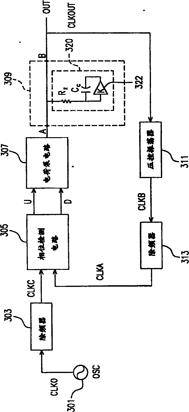
[0041] image 3 is a circuit block diagram of a phase-locked loop according to an embodiment of the present invention. see image 3 As shown, the output of the oscillator 301 is sent to the frequency divider 303 and coupled to the phase detection circuit 305 through the frequency divider 303 . The phase detection circuit 305 charges or discharges the loop filter 309 through the charge pump circuit 307 . The output terminal B of the loop filter 309 is coupled to the output OUT of the phase-locked loop of the present invention, and is coupled to the input of the voltage-contr...


PUM


Abstract

This invention relates to a phase-lock loop and its applied loop filter including a first resistor, a first capacitor and an amplifier with a specific gain value, among which, the amplifier has an input end coupled to the input and output ends of the loop filter by the first resistor, the amplifier has an output end coupled to the input end of the amplifier via the first capacitor.

Description

technical field [0001] The invention relates to a loop filter, in particular to a phase-locked loop with a fast setting and small-area loop filter architecture and a loop filter applied thereto. Background technique [0002] In general, there are extremely important timing requirements in electronic or computer systems. Therefore, the periodic pulse signal provided to the system must be precisely synchronized with the reference pulse signal. A Phase Locked Loop (PLL for short) is a widely used circuit, which can precisely control the frequency of an output signal to achieve synchronization with the frequency of an input signal. PLLs are often used in frequency synthesizers, multipliers, dividers, single and multiple pulse signal generators, pulse signal recovery circuits, and wireless communication devices, etc. [0003] figure 1 It is a circuit block diagram of a conventional phase-locked loop. see figure 1 As shown, the output of an oscillator 101 , such as a crystal ...

Claims


Application Information

Patent Timeline
Patent Type & Authority Patents(China)
IPC IPC(8): H03L7/08H03L7/085H03L7/093
Inventor 刘智民
Owner VIA TECH INC
Why Eureka
Try Eureka