Melamine and ammonium carbonate joint production technology

A technology of melamine and process is applied in the field of co-production process of melamine and ammonium bicarbonate to achieve the effects of saving power consumption, low manufacturing cost and convenient operation

Inactive Publication Date: 2005-08-10
尹明大
View PDF0 Cites 6 Cited by
  • Summary
  • Abstract
  • Description
  • Claims
  • Application Information

AI Technical Summary

Problems solved by technology

[0003] The purpose of the present invention is to provide a co-production process of melamine and ammonium bicarbonate to solve many deficiencies in the existing domestic production process of melamine under atmospheric pressure.

Method used


Image

  • Melamine and ammonium carbonate joint production technology

Examples


Embodiment Construction

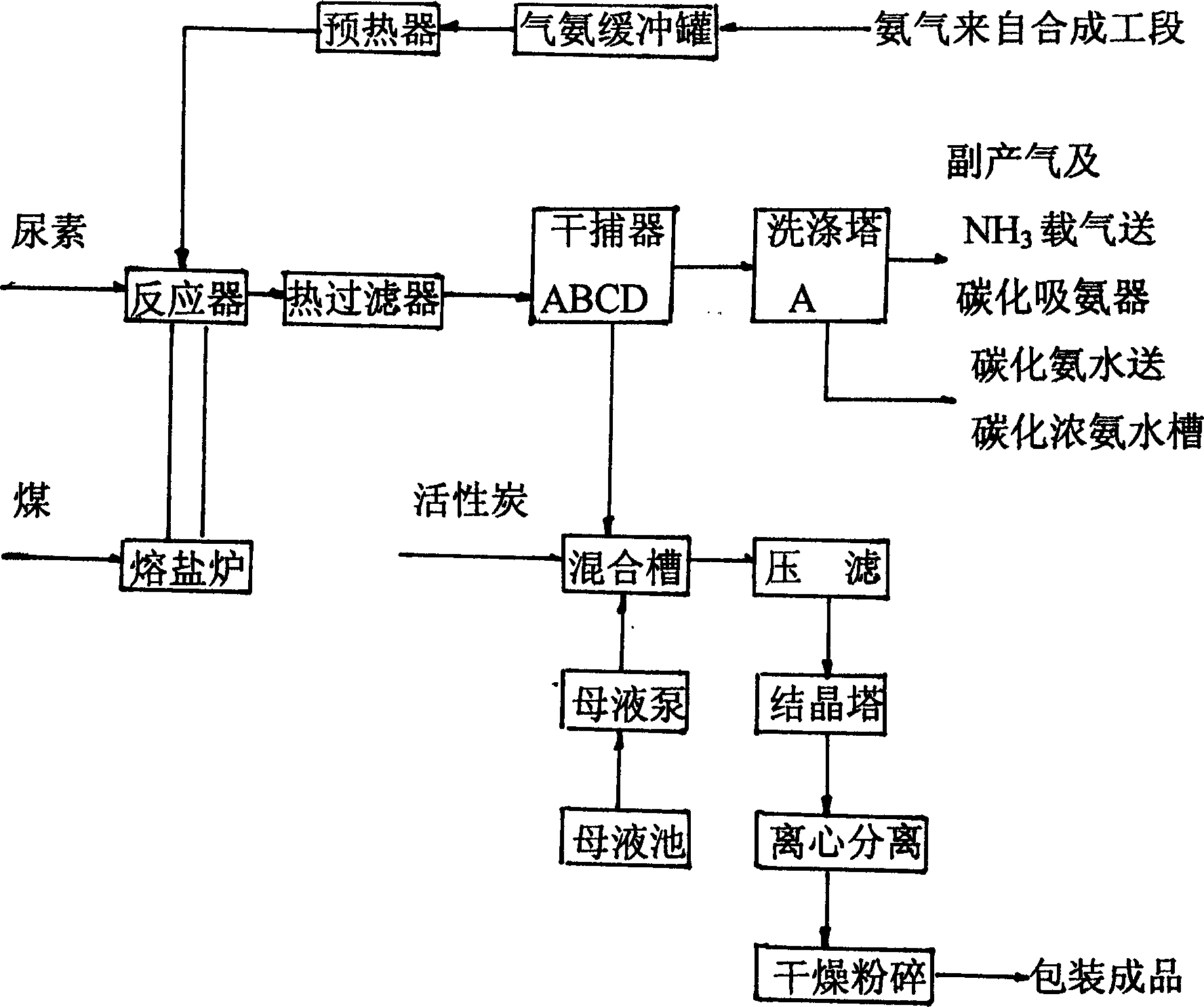
[0019] Referring to Figure 1, the co-production process of melamine and ammonium bicarbonate is to preheat the 0.10-0.20Mpa pure ammonia gas from the synthetic ammonia cooler to 250-350°C through steam and molten salt, and then enter the flow stream from the bottom of the fluidized bed. The fluidized bed reactor is used as the carrier gas, and the urea that is pressed into the feeder with air is sent into the fluidized bed. Under the action of the catalyst, it is decomposed at 370-420°C under normal pressure to produce melamine and The reaction gas of carbon dioxide and ammonia; the reaction gas is roughly filtered by the hot gas filter and then enters the dry trap to cool down naturally, so that the melamine in the reaction gas is precipitated and the crude melamine is obtained after 5-7 days of parking; and it contains carbon dioxide, ammonia and carrier gas The tail gas of ammonia is preliminarily washed with ammonia water to remove dust and cool down, and then enters the am...


PUM


Abstract

A process for preparing cyanuramide and ammonium dicarbonate includes preheating ammonia gas as carrier, introducing it to fluidized-bed reactor, pumping urea in said reactor, high-temp catalytic decomposing to generaet the reactive gas containing cyanuramide, CO2 and ammonia, filtering, cooling to educe out cyanuramide, washing the tail gas by ammonia water, coding, carbonizing to obtain cabonized ammonia water, preparing ammonium dicarbonate, mixing said cyanuramide with its mother liquid, thermal dissolving, filtering, cooling for crystallizing, centrifugal separating, drying and pulverizing to obtain finished cyanuramide.

Description

technical field [0001] The invention relates to a process for producing melamine, in particular to a co-production process of melamine and ammonium bicarbonate. Background technique [0002] The current production of melamine, such as taking the existing domestic melamine production enterprises with an annual output of 1,000 tons as an example, adopts the domestic normal pressure production process, that is, in the production process, ammonia is used as the carrier gas and the tail gas is recycled. Since no water is allowed in the urea synthesis reaction of melamine, the carrier gas ammonia must be separated and removed by ammonia cold drying. plus CO in the exhaust 2 After washing, the whole device needs to have a tail gas washing system, an ammonia cold drying system, and an ammonia gas circulation system, resulting in a large investment in the whole device. Due to the exhaust gas circulation in the existing domestic atmospheric production proc...

Claims


Application Information

Patent Timeline
IPC IPC(8): C01C1/26C07D251/56
Inventor 尹明大
Owner 尹明大
Why Eureka
Try Eureka