In-cavity aberration detection system and cavity regulating method for lineal confocal unstable cavity

A detection system and a technology of unstable cavity, which are applied in the field of aberration detection system in resonator cavity and cavity tuning of resonator cavity, can solve the problem that the phase characteristics of the beam cannot be directly reflected, the guiding significance of the adjustment of the optical cavity is not obvious, and the device is not resistant. Strong light irradiation and other problems, to achieve the effect of strong anti-interference ability, shortened waiting time and simple structure

Inactive Publication Date: 2005-09-07
INST OF OPTICS & ELECTRONICS - CHINESE ACAD OF SCI
View PDF0 Cites 9 Cited by
  • Summary
  • Abstract
  • Description
  • Claims
  • Application Information

AI Technical Summary

Problems solved by technology

Although this method can intuitively see the near-field and far-field intensity modes of the beam, the obvious disadvantage is that it cannot directly reflect the phase characteristics of the beam, and it does not subdivide the comprehensive effect reflected into each order of optical aberration. meaning is not obvious
[0005] D.Anafi et al. studied positive branch confocal cavity CO in "Intracavity Adaptive Optics.2: Tilt Correction performance", Applied Optics, Vol. 2 In the adaptive optics correction of laser intracavity aberration, an intracavity beam splitter (Intracavity BeamSplitter) with a reflectivity of 3% is placed near the intracavity coupling output mirror to directly detect the intracavity intensity mode. The advantage is that it can directly reflect Intra-cavity light intensity mode, but its disadvantage is that its own aberration may directly affect the coupled output cavity mode, and even generate high-order modes, and this type of device is generally not resistant to strong light, so it cannot be directly placed in a high-energy laser. detection

Method used


Image

  • In-cavity aberration detection system and cavity regulating method for lineal confocal unstable cavity
  • In-cavity aberration detection system and cavity regulating method for lineal confocal unstable cavity
  • In-cavity aberration detection system and cavity regulating method for lineal confocal unstable cavity

Examples


Embodiment Construction

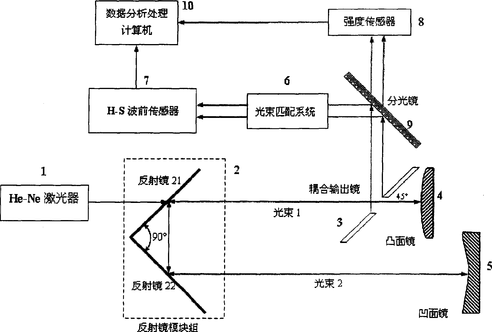
[0030] Such as figure 1As shown, the detection system of the present invention consists of a He-Ne laser 1, a positive branch confocal cavity mirror group, a beam splitter 9, an optical matching (beam expansion or contraction) system 6, a Hartmann-Shack wavefront sensor 7, and a four-way Limit intensity sensor 8 and data processing and analysis computer 10, wherein the positive branch confocal cavity is a folded cavity, including two 45° reflector groups 2, coupling output mirror 3, convex reflector 4, concave reflector Mirror 5 constitutes, wherein the angle between the first reflector 21 and the second reflector 22 in the 45° reflector group 2 is 90°, and the convex reflector 4 is located at the first reflector with the coupling hole in the 45° reflector group 2 21 (The purpose of having a coupling hole on the first reflecting mirror 21 is to make the He-Ne light 1, also known as cavity-tuned light, be fully coupled into the resonator to check the adjustment state of the opt...


PUM


Abstract

The invention relates to a system for adjusting the confocal unsteady cavity and detecting the optical aberration, characterized in that it comprises a He-Ne light source, a confocal unsteady cavity lacuna, a light beam matching telescope, a Hageman sensor, a four-quadrant intensity sensor, an image collecting card and a computer, wherein the confocal unsteady cavity lacuna comprises the 45 deg. reflecting mirror group, coupling output mirrors, convex reflecting mirrors and concave reflecting mirrors. The invention can adjust the optical cavity coaxials quickly, and can detect, process and decide the optical aberration in the cavity.

Description

Technical field [0001] The invention relates to an intracavity aberration detection system of a resonant cavity used in an optical detection system and a cavity tuning method thereof, in particular to a positive branch confocal unstable cavity tuning and aberration detection system and a cavity tuning method thereof. Background technique [0002] Since the working wavelength of lasers with positive branch confocal unstable cavity structure is generally in the infrared region, it is very important whether the resonator is adjusted before working. This is one of the important prerequisites to ensure better beam quality output by the resonator. At present, some predecessors have made some explorations and attempts in this regard. [0003] Jack Hanlon et al propose a method in "Alignment Technique for Unstable Resonators", Jack Hanlon and Steve Aiken, Applied Optics, Vol.13, No.11, November1974, pp.2461, that is, insert a strip near the concave cavity mirror The 45° mirror of t...

Claims


Application Information

Patent Timeline
Patent Type & Authority Applications(China)
IPC IPC(8): G01J1/02G01J9/00G01M11/02
Inventor 张翔许冰
Owner INST OF OPTICS & ELECTRONICS - CHINESE ACAD OF SCI
Why Eureka
Try Eureka