High thermal conductivity insulating member and its manufacturing method, electromagnetic coil, and electromagnetic device
A technology of insulating components and high thermal conductivity, which is applied in the direction of transformer/inductor coil/winding/connection, coil, insulator, etc., which can solve the problems of insufficient thermal conductivity, labor-intensive manufacturing, and increased cost to achieve excellent heat dissipation characteristics Effect
- Summary
- Abstract
- Description
- Claims
- Application Information
AI Technical Summary
Problems solved by technology
Method used
Image
Examples
no. 1 Embodiment approach
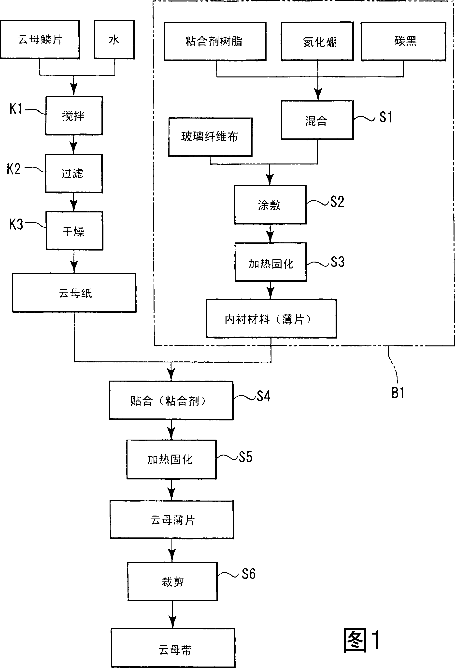
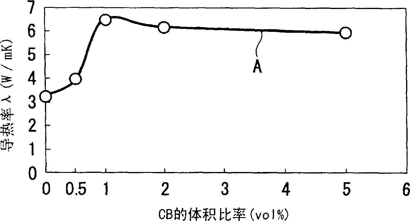
[0075] Below, refer to Figure 1- Figure 8 The first embodiment of this embodiment will be described.
[0076] First, production of the mica tape of this embodiment will be described with reference to FIG. 1 .
[0077] Mix 3000cc of water into 2.826g of mica flakes, and stir (process K1). In this case, a small amount of epoxy resin can also be added as an adhesive.
[0078] According to the procedure of papermaking, the above-mentioned stirred mixture is passed through, for example, a 0.5 mm×0.5 mm grid to prepare a green sheet (step K2). This green sheet is heated at a predetermined temperature and dried to obtain a mica paper 1 (step K3).
[0079] In the lining material manufacturing process B1 of this embodiment, first, the binder resin, boron nitride particles, and carbon black particles are mixed in a mass ratio of 24.7:74.2:1.1 and mixed (step S1) . In this example, Asahisa-Mal (trade name) manufactured by Asahi Kabon (Carbon Black) Co., Ltd. was used as the carbon ...
no. 2 Embodiment approach
[0108] Next, refer to Figure 9- Figure 11 The second embodiment will be described.
[0109] In the member of this embodiment, the mica layer is filled with highly thermally conductive particles. Lining material adopts glass fiber cloth 25. 2.83 g of mica flakes and 0.125 g of alumina particles were mixed into 3000 cc of water, followed by stirring (step S21). In this example, NanoTek Al 2 O 3 -HT (product model) manufactured by Nippon Shi-ai Chemicals Co., Ltd. was used as the alumina particles. The average particle diameter of the alumina particles was 70 μm. The shape of the alumina particles is spherical. The mica flakes are made of sintered mica. The average particle size of mica flakes is 15 μm.
[0110] According to the procedure of papermaking, the above-mentioned stirred mixture is passed through, for example, a 0.5 mm×0.5 mm grid to prepare a green sheet (step S22 ). This green sheet was heated and dried at 120° C. to obtain a mica paper (step S23 ).
[0111]...
no. 3 Embodiment approach
[0115] Below, refer to Figure 12 The third embodiment will be described. In the mica tape 10A of this embodiment, the mica layer 9 is filled and dispersed with first particles having a thermal conductivity of 0.5 W / mK or more. In this embodiment, the mica layer 11 is manufactured by a common method, and the lining material is a thermally conductive sheet 9 with high thermal conductivity. In this case, the mica layer 11 functions as a thermal barrier since the thermal conductivity of the mica layer 11 is small compared with the lining material layer 9 .
[0116] Here, when forming the mica paper, the alumina particles with an average particle diameter of 70 nm and the mica paper were mixed. Specifically, mica paper and alumina particles were stirred in distilled water, coated on glass fiber cloth having a mesh size of 0.05 μm, and dried to form mica flakes. The mica sheet itself has a thermal conductivity of about 0.6 W / mK, but if the mica layer 11 formed of only mica paper...
PUM
| Property | Measurement | Unit |
|---|---|---|
| Thermal conductivity | aaaaa | aaaaa |
| Thermal conductivity | aaaaa | aaaaa |
| The average particle size | aaaaa | aaaaa |
Abstract
Description
Claims
Application Information
 - R&D
- Intellectual Property
- Life Sciences
- Materials
- Tech Scout
- Unparalleled Data Quality
- Higher Quality Content
- 60% Fewer Hallucinations
Browse by: Latest US Patents, China's latest patents, Technical Efficacy Thesaurus, Application Domain, Technology Topic, Popular Technical Reports.
© 2025 PatSnap. All rights reserved.Legal|Privacy policy|Modern Slavery Act Transparency Statement|Sitemap|About US| Contact US: help@patsnap.com


