
Plasticizing system of conveying belt production line

A production line and conveyor belt technology, which is applied in the field of equipment for producing belts, can solve the problems of large energy consumption, hidden dangers, and low product level, and achieve the effects of improving heat exchange efficiency, safe and reliable production, and stable product performance.

Inactive Publication Date: 2005-09-21
CHINA COAL TECH & ENG GRP SHANGHAI RES INST
View PDF0 Cites 2 Cited by
  • Summary
  • Abstract
  • Description
  • Claims
  • Application Information

AI Technical Summary

Problems solved by technology

[0003] 1. The temperature in the plasticizing box of the plasticizing system is unbalanced: In the plasticizing box of the plasticizing system, due to the continuous heating of the electric heating pipe row, the hot air in the box naturally flows upwards, and the cold air in the lower part of the box is constantly Entering, the temperature distribution in the entire plasticizing box is higher towards the top of the box, and the temperature difference between the upper and lower sides of the plasticizing box may reach 40-50°C, which is difficult to meet the process requirements, so the product level provided is lower (product Most of the levels are concentrated below level 8), which cannot meet the needs of mine production and development
[0004] 2. Due to the long residual heat of the heat source in the plasticizing box, when the power is suddenly cut off or shut down, it may cause adhesion, scorching or fire to the impregnated belt in the box, which poses a great safety hazard
[0005] 3. Large power consumption: the heat transfer efficiency of the electric heating pipe row is low, and the temperature in the plasticizing box is not balanced, and the temperature required for the plasticizing box is relatively high. In order to ensure that the temperature in the plasticizing box reaches the overall core plasticization temperature requirements, must consume a large amount of energy
[0006] 4. The structure of the electric heating pipe row is complicated, and a large number of electric heating elements are required, so failures and unsafe phenomena are prone to occur, and it is also difficult to replace and repair a large number of electric heating elements, and the cost of use is also increased, which is very uneconomical

Method used


Image

  • Plasticizing system of conveying belt production line
  • Plasticizing system of conveying belt production line
  • Plasticizing system of conveying belt production line

Examples


Embodiment Construction

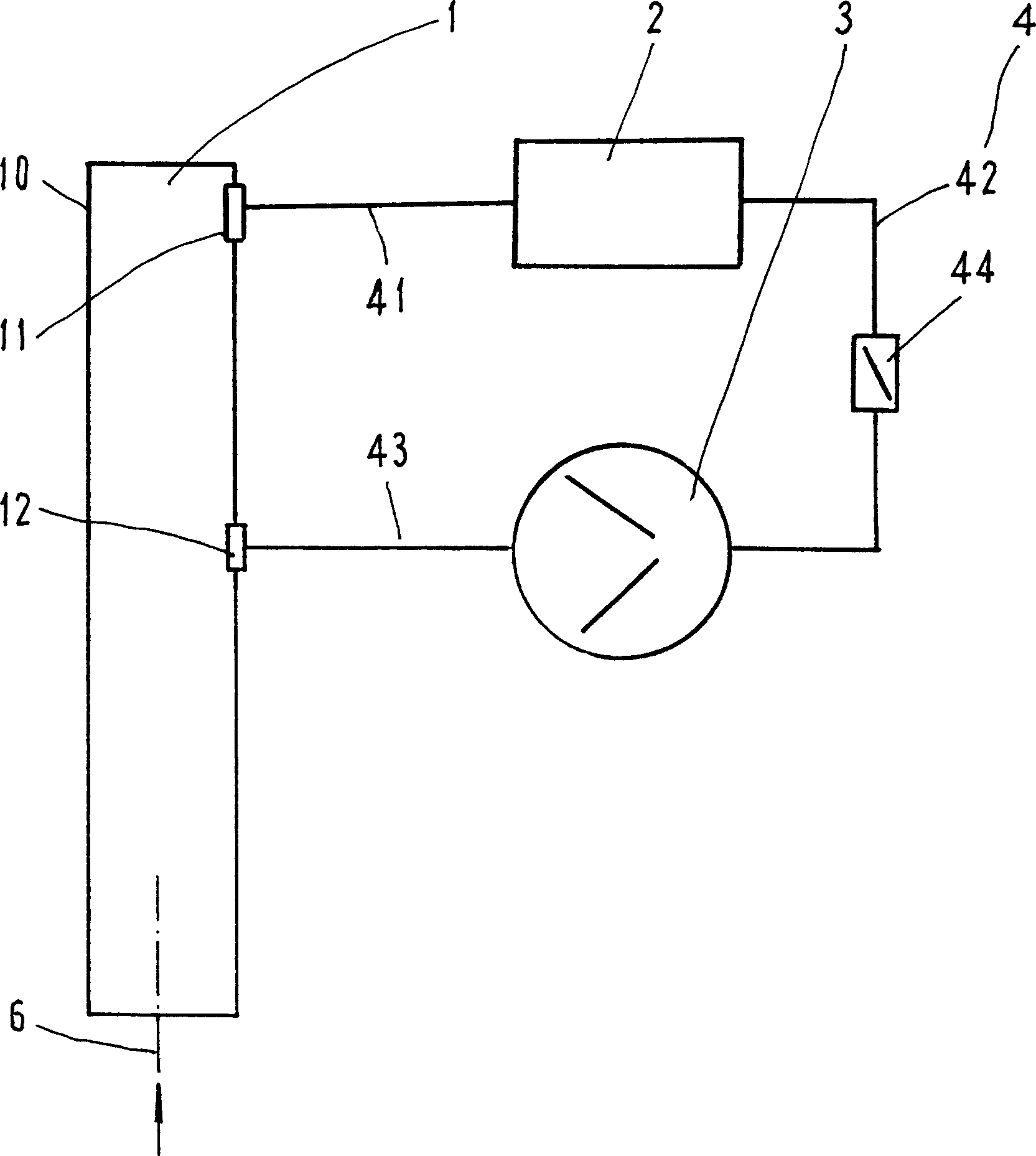
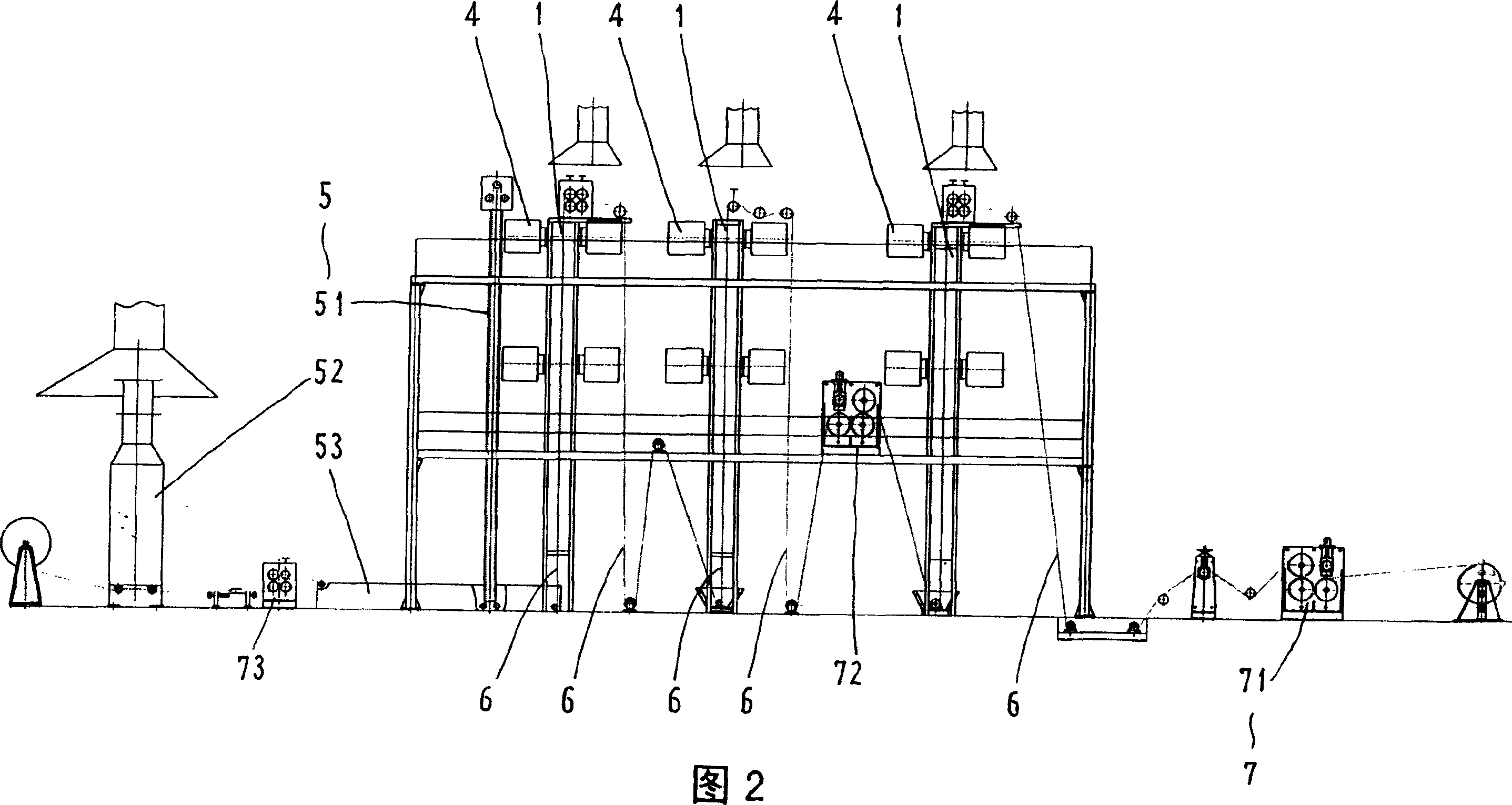
[0020] refer to figure 1 , 2. The conveyor belt production line includes: a set of plasticizing system, front equipment 5, traction system 7 and control system, etc. The overall belt core 6 is stretched through the front equipment 5 and plasticization system, and is pulled by the traction system 7 Advance; front equipment 5 includes equipment such as vacuum tower 51, drying oven 52 and dipping tank 53; Traction system 7 includes main tractor 71, auxiliary tractor 72 and drying tractor 73, wherein main tractor 71 is arranged on the whole At the output end of the belt core 6, the auxiliary tractor 72 is arranged in the middle of the plasticizing system, and the drying tractor 73 is arranged between the drying box 52 and the dipping tank 53; °Turn, each turning point is evenly equipped with guide rollers to guide the overall belt core with 6 turns; the production line is equipped with a full-process control system to achieve good management and strict quality control.

[0021] T...


PUM


Abstract

This invention relates to transmission band production line plastic system, which adopts the following technique scheme: each plastic system comprises plastic case, heat exchanger, wind drawing pipe separately connected with heat exchanger and fan and the wind in pipe is separately connected with wind-in mouth and fan, plastic case, heat exchanger and fan to form one sealed heat air recycling system suitable for each core transmission band production line.

Description

Technical field: [0001] The invention relates to a device for producing strips, in particular to a plasticizing system in a conveyor belt production line. Background technique: [0002] The whole core conveyor belt is widely used in mines, steel plants, ports and other places, especially the indispensable link in the coal mine production and transportation equipment. At present, the production of the whole core conveyor belt mostly adopts "electric heating type coating scraping and extrusion The corresponding equipment includes drying oven, dipping tank, vacuum tower, traction system, plasticizing system and control system. Tank impregnation, then the tape core is introduced into the vacuum negative pressure tower, and the integral tape core filled with dipping paste is plasticized in the plasticizing system, and finally cooled and shaped; the traction system includes a dry tractor, an auxiliary tractor and a main tractor. The system is equipped with corresponding guide rol...

Claims


Application Information

Patent Timeline
IPC IPC(8): B29C35/06B29K
Inventor 顾亚民王利平周国庆
Owner CHINA COAL TECH & ENG GRP SHANGHAI RES INST
Learn More