Ultrasonic wire welding method and apparatus

A wire welding device and ultrasonic technology, which is applied in the direction of welding equipment, non-electric welding equipment, electrical components, etc., can solve the problems of machine welding wire efficiency reduction, difficulty in improving welding wire accuracy, and large position deviation, so as to save identification time , improve efficiency, improve the effect of precision

Inactive Publication Date: 2005-09-28
曹相梅
View PDF0 Cites 14 Cited by
  • Summary
  • Abstract
  • Description
  • Claims
  • Application Information

AI Technical Summary

Problems solved by technology

Using point-to-point positioning for LED wire bonding is to first confirm two points on the PCB as the reference point, and then confirm the position of each point of the LED first, and then solder the wire. The time spent on confirming the position greatly improves the efficiency of machine soldering wire. lower, usually by nearly 50%
In order to save the time spent on confirming the position when using point-to-point positioning for IC chip bonding, it is only necessary to first confirm two points on the

Method used


Image

  • Ultrasonic wire welding method and apparatus
  • Ultrasonic wire welding method and apparatus
  • Ultrasonic wire welding method and apparatus

Examples


Embodiment Construction

[0053] A rotary automatic ultrasonic wire welding machine

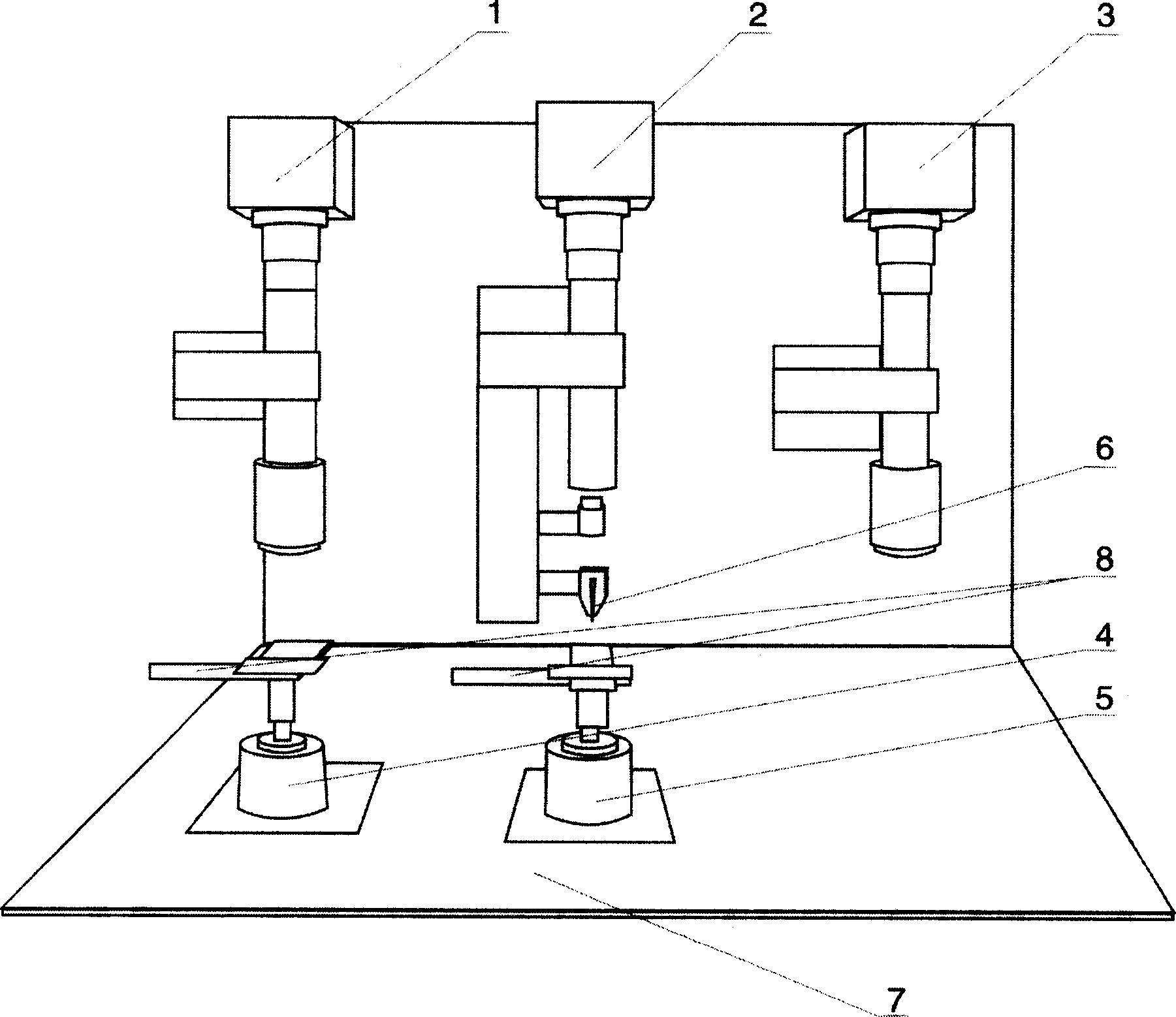
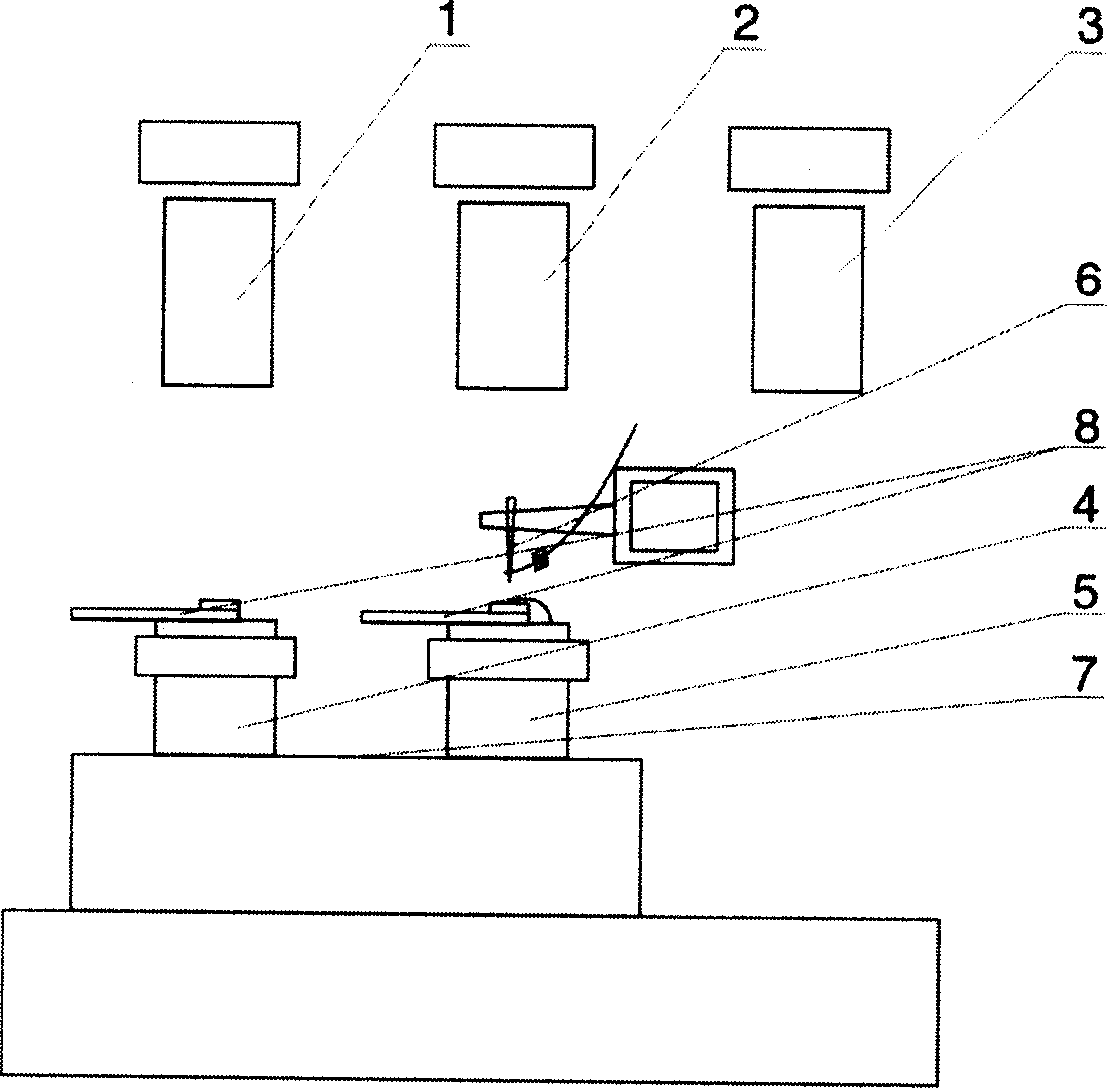
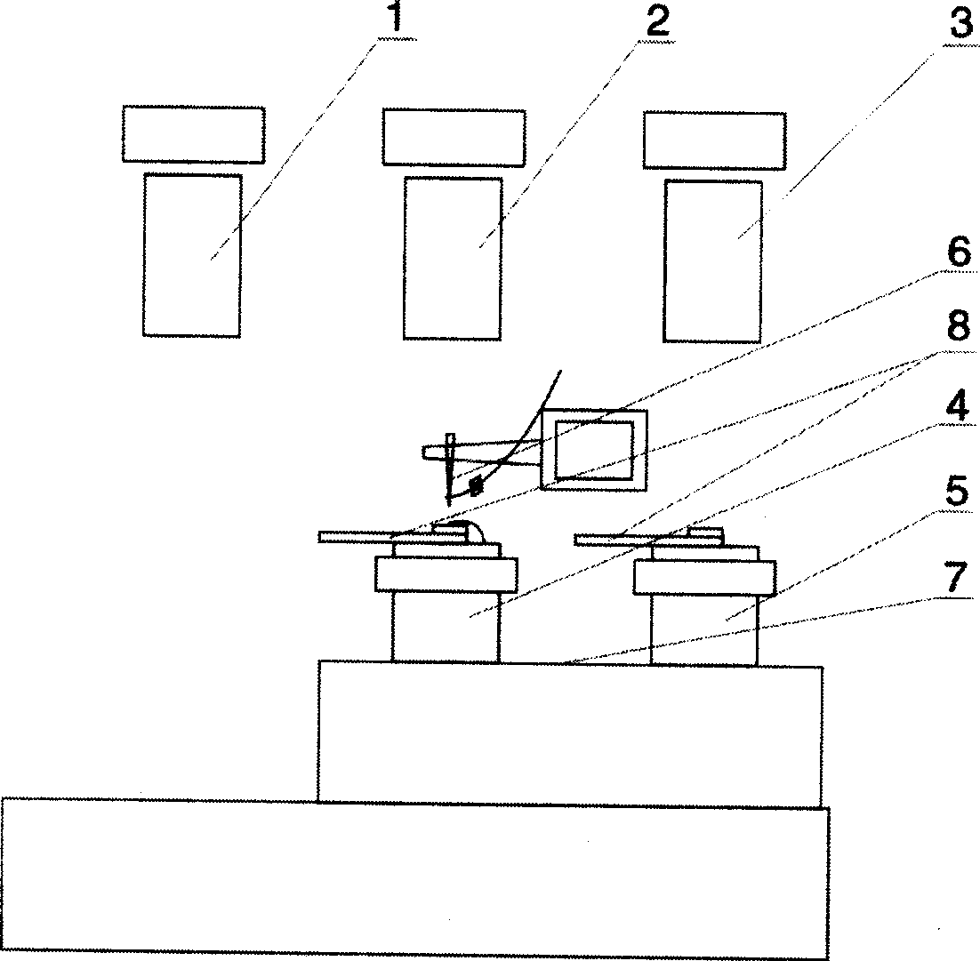
[0054] Such as figure 1 , 2 . The rotary table-type automatic ultrasonic wire bonding machine shown in 3 includes a welding head system 2, an X-Y workbench 7 that can move in the horizontal direction, and a Θ turntable 4 and 5 that can rotate in the horizontal direction on a group of X-Y workbenches 7 , the welding head system 2 is provided with an image optical system including an adjustable optical lens group and a camera for checking the quality of the welding wire, a Z table that can move in the vertical direction, including a transducer, a welding nozzle 6, Send and pull the welding head of line parts and wire clip, be positioned at the center of the X direction of X-Y workbench 7, described optical lens group and welding head are fixed on Z workbench and can move in vertical direction, on described Θ turntable 4,5 A jig 8 for wire welding workpieces is provided.

[0055] There are also two sets of imaging opt...


PUM


Abstract

The present invention discloses one kind of ultrasonic wire welding method and apparatus. The welding apparatus includes two locating optical imaging systems with optical lens set and camera; and two horizontal turntables on the X-Y work benches with two exchangeable work sites each. When one of the two horizontal turntables locates under one of the two locating optical imaging systems, the other welds in the other optical imaging systems, and the course is exchanged and repeated. The present invention has raised LED wire welding efficiency, and increased IC chip wire welding area.

Description

technical field [0001] The present invention relates to a welding method or equipment suitable for semiconductors, solid devices or parts thereof used for conducting electric current leads, in particular to an ultrasonic wire welding method and a wire welding device. Background technique [0002] The integrated circuit chip IC or light-emitting diode LED is directly packaged on the circuit board PCB or the chip on the substrate (Chip on Board, referred to as COB), which has been widely used in such as computers, mobile phones, optical digital products, smart cards, clocks, Toys and other consumer electronic information products. Wire bonding is the basic process of COB, which requires the use of ultrasonic wire bonding methods and corresponding equipment. There is an automatic ultrasonic wire bonding machine specially used for bridging IC chips or LEDs with multiple wires and the corresponding pads on the PCB, including a welding head system, an X-Y table that can move in t...

Claims


Application Information

Patent Timeline
IPC IPC(8): B23K20/10H01L21/607
CPCH01L2224/78H01L24/78H01L2924/01082H01L2924/00014B23K20/10H01L2224/78313H01L2224/78621H01L2224/78631H01L2924/14H01L2224/48H01L2924/00H01L2224/45099
Inventor 陈卢坤
Owner 曹相梅
Why Eureka
Try Eureka