Acoustic surface-wave oscillator system for gas sensor

A gas sensor, surface acoustic wave technology, applied in the direction of electrical components, impedance networks, etc., can solve the problems of temperature drift, poor substrate temperature stability, increase system power consumption, etc., to improve frequency stability, reduce insertion loss, Effect of Power Consumption Reduction

Inactive Publication Date: 2005-10-05
INST OF ACOUSTICS CHINESE ACAD OF SCI +1
View PDF0 Cites 20 Cited by
  • Summary
  • Abstract
  • Description
  • Claims
  • Application Information

AI Technical Summary

Problems solved by technology

The three delay lines all use the same number of transducer fingers (50 pairs), the acoustic aperture is 80 times the wavelength, the finger width and inter-finger spacing are both 1 / 4 wavelength, and the transducer spacing is 264 times and 166 times respectively. times and 350 times the wavelength, the substrate is ST quartz, and the losses of these three kinds of delay lines are all greater than 20dB
[0004] 1. The surface acoustic wave delay line itself cannot solve the mode control problem of the surface acoustic wave oscillator, and can only be solved by external circuits, which will inevitably make the circuit complex, increase the power consumption of the system, and affect the compact structure of the sensor system and temperature stability
[0005] 2. The quartz-based delay line used in the existing surface acoustic wave gas sensors usually adopts a conventional single-finger or double-finger structure, resulting in excessive loss (usually greater than 20dB); therefore, the oscillation circuit requires the use of High-gain RF amplifier to compensate for device and component loss in the circuit
However, the temperature stability of this kind of substrate is very poor, which will cause serious temperature drift, which will affect the frequency stability of the surface acoustic wave oscillator, and then affect the sensitivity of the gas sensor.
Moreover, in the application of surface acoustic wave gas sensors using such substrates, constant temperature and humidity control devices must be provided, which obviously increases the burden on electronic circuits and does not meet the requirements of miniaturization and portability of gas sensors.

Method used


Image

  • Acoustic surface-wave oscillator system for gas sensor
  • Acoustic surface-wave oscillator system for gas sensor
  • Acoustic surface-wave oscillator system for gas sensor

Examples


Embodiment Construction

[0041] For a fuller understanding of the invention, with additional objects and advantages thereof, reference should now be made to the following detailed description of the invention taken in conjunction with the accompanying drawings.

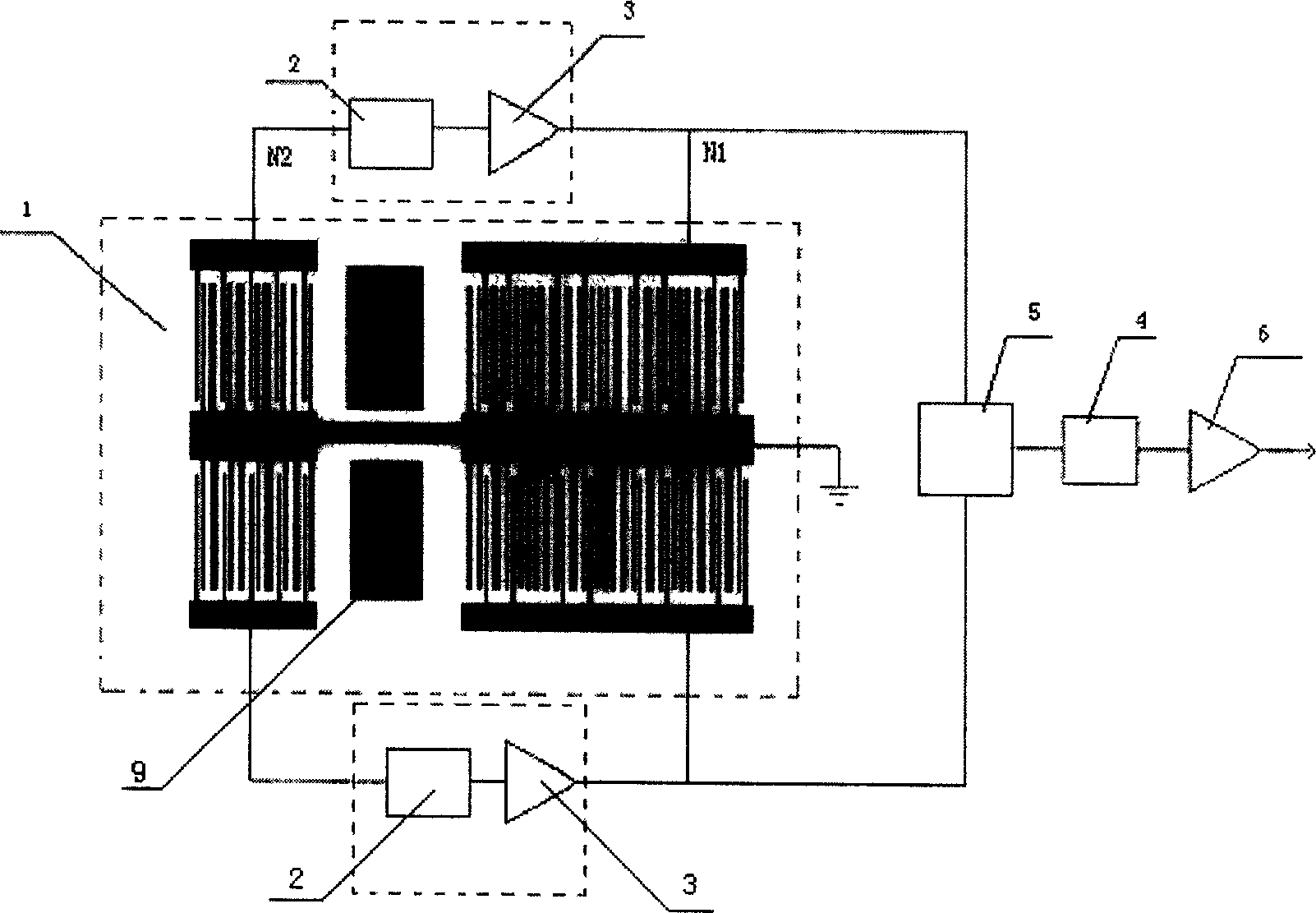
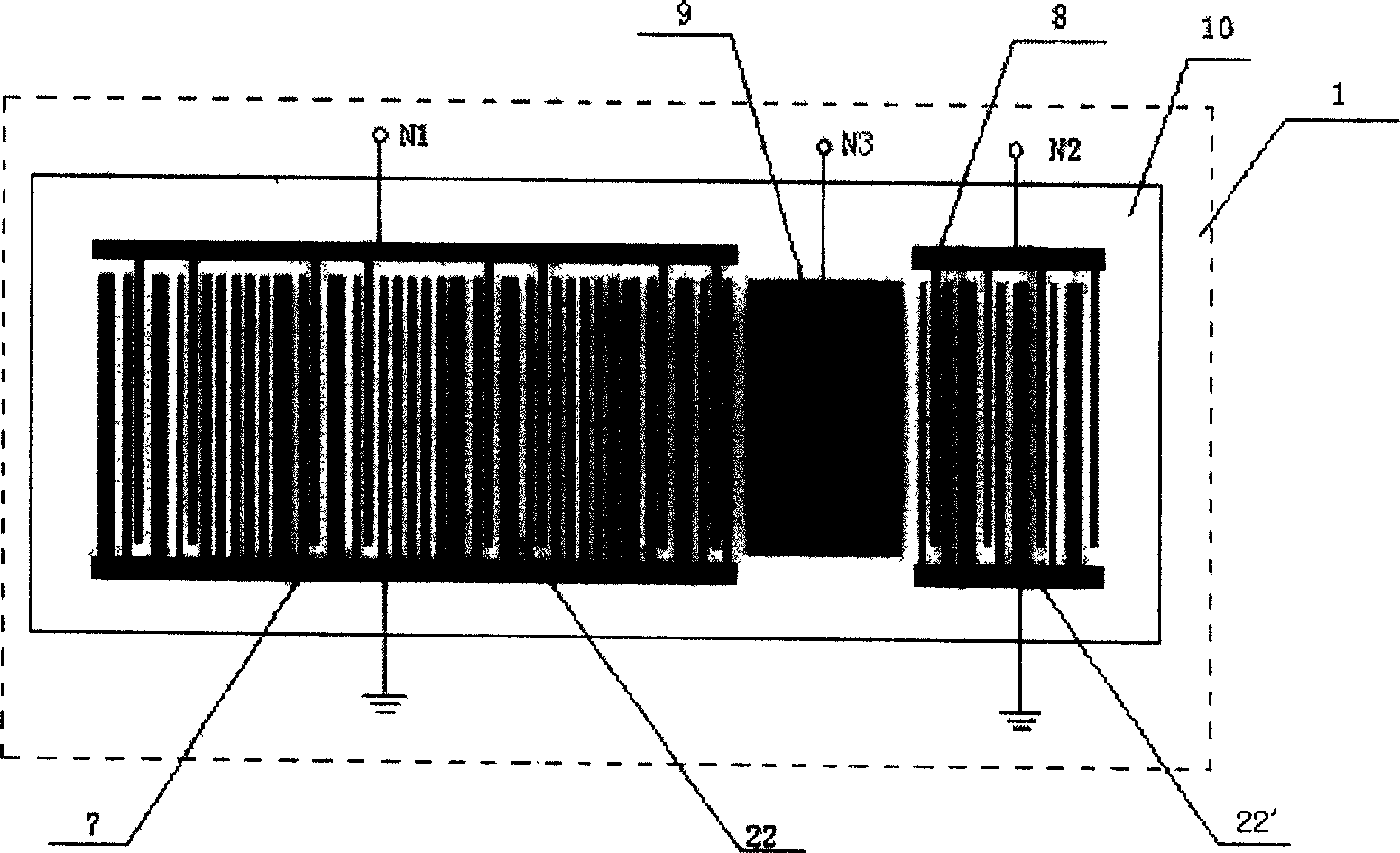
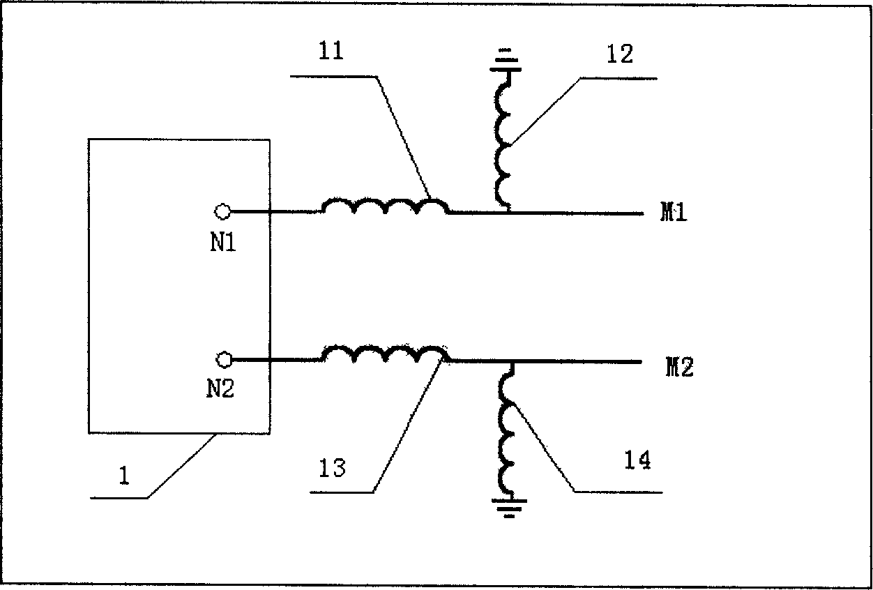
[0042] refer to figure 1 , making a surface acoustic wave oscillator system applied to gas sensors, by figure 1 It can be seen that the oscillator system consists of two sets of SAW oscillators, a set of conventional mixers 5, a conventional low-frequency amplifier 6 and a general low-pass filter 4, and each set of SAW oscillators consists of a A surface acoustic wave delay line 1, a conventional radio frequency amplifier 3, and a phase shifting network 2 are formed. Delay line 1 acts as the feedback element for the overall oscillator. Two sets of delay lines are fabricated on the same substrate. Depend on figure 1 The workflow of the surface acoustic wave oscillator applied to the gas sensor according to the scheme of the present inventi...


PUM


Abstract

The disclosed system comprises two groups of acoustic surface wave oscillator composed of acoustic surface wave delay line, radio frequency amplifier and phasing network, and one group of mixer circuit composed of mixer, low frequency amplifier and low pass filter. Outputs of two groups of oscillator are connected to the mixer. The output of the mixer passing through low pass filter and low frequency amplifier outputs signal of difference frequency between two groups of oscillator. Two groups of delay line are fabricated on same substrate. Single-phase unidirectional transducer (SPUDT) structure is adopted in delay line so as to reduce insertion loss. Length of the long transducer is equal to distance between geometric centers of transducers. Comb structure is adopted, and gap between combs is equal to length of the short transducer in order to restrain unwanted mode of oscillation. The oscillator is operated at single mode so as to raise frequency stability (0.07 ppm).

Description

technical field [0001] The present invention relates to an oscillator, and more particularly to a surface acoustic wave ("SAW") oscillator system for a gas sensor. Background technique [0002] As we all know, the core component of a gas sensor is a high frequency and high stability oscillator. Generally, there are roughly two types of such high-stability oscillators in practical applications, one is crystal oscillators, but studies have shown that the sensitivity of sensors is approximately proportional to the square of the oscillation frequency, while the oscillation frequency of crystal oscillators is generally not Greater than 30MHz, therefore, crystal oscillators cannot be used for gas sensors with higher sensitivity requirements. The other is the surface acoustic wave oscillator. This oscillator has high frequency stability. The operating frequency of this SAW device is two orders of magnitude higher than that of the crystal oscillator. Therefore, the gas used in this...

Claims


Application Information

Patent Timeline
Patent Type & Authority Applications(China)
IPC IPC(8): H03H9/00H03H9/25
Inventor 何世堂王文李训洲潘勇黄启斌余建华
Owner INST OF ACOUSTICS CHINESE ACAD OF SCI
Why Eureka
Try Eureka