Plasma cutting torch

A plasma and cutting torch technology, applied in the direction of plasma, plasma welding equipment, electrical components, etc., can solve the problems of shortened life, poor cutting performance, difficult to maintain the shaft core, etc., to achieve longer life and stable cutting performance. Effect

Inactive Publication Date: 2005-10-05
DAIHEN CORP
View PDF0 Cites 8 Cited by
  • Summary
  • Abstract
  • Description
  • Claims
  • Application Information

AI Technical Summary

Problems solved by technology

Therefore, only the axial center of the electrode 7 changes a little, and it is difficult to keep the axial center of each of the electrode 7 and the plasma nozzle 9 on the same axis.
Therefore, when the main plasma arc moves, since the plasma arc is not generated in the axis direction, there is a disadvantage that the cutting performance deteriorates.
[0015] In addition, since the axes of the electrodes 7 and the plasma nozzles 9 are not on the same axis, the electrodes 7 and the plasma ejection holes 9a are unevenly worn, and the service life thereof is shortened.

Method used


Image

  • Plasma cutting torch
  • Plasma cutting torch
  • Plasma cutting torch

Examples


Embodiment approach 1

[0029] Embodiments of the invention will be described based on examples with reference to the drawings.

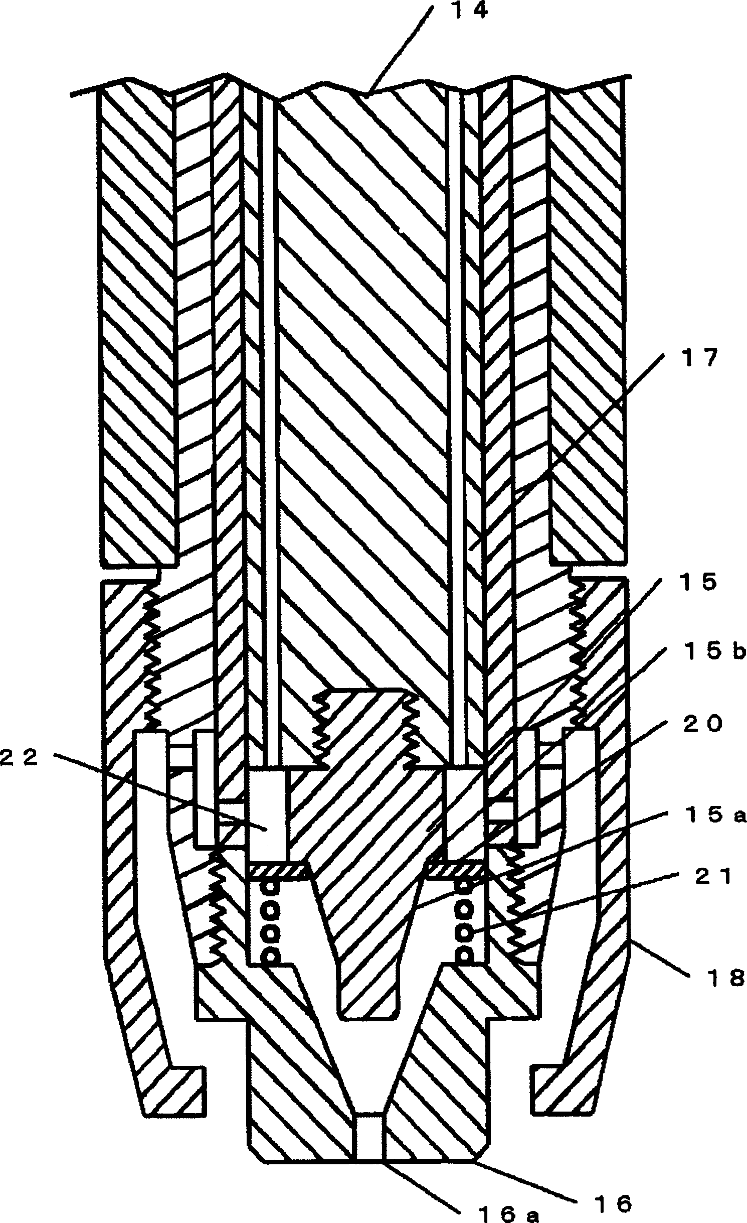
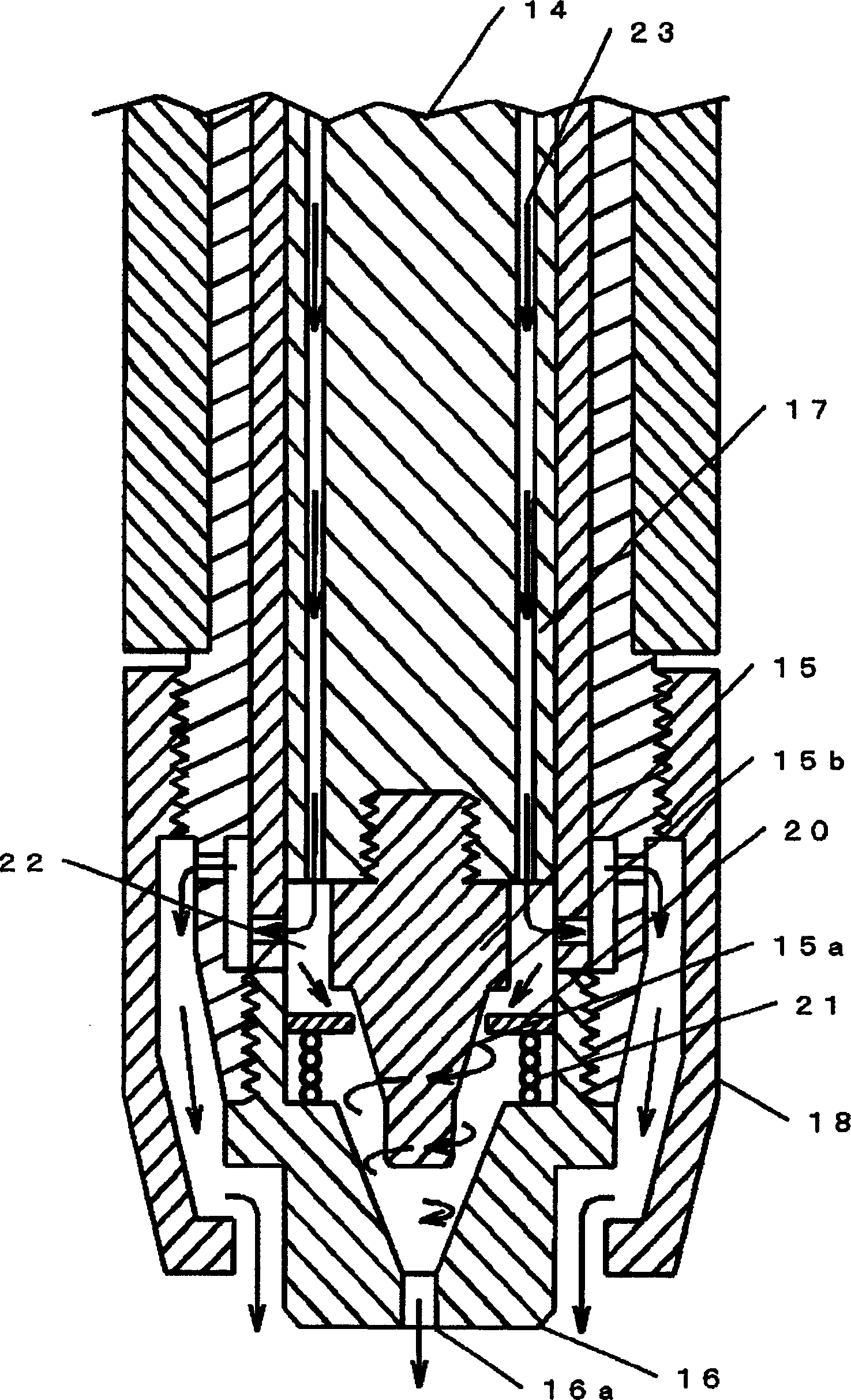
[0030] figure 1 as well as figure 2 It is a sectional view of the plasma cutting torch of the present invention. figure 1 Indicates the state before the plasma gas is supplied, figure 2 Indicates the status when plasma gas is supplied.

[0031] exist figure 1 Among them, an electrode 15 is installed on the shaft core of the torch body 14 (usually hafnium is embedded in the front end of the copper electrode), and a tapered portion 15a is formed on the front end of the electrode 15 . A main plasma arc is generated between this electrode 15 and the workpiece 3 . The plasma nozzle 16 is installed on the torch body 14 , is cylindrical and has conductivity, is coaxial with the electrode 15 , and generates a pilot arc between the electrode 15 and the electrode 15 . In addition, a plasma ejection hole 16a is formed on the front end portion. A cylindrical insulating mem...


PUM


Abstract

The present invention provided a plasma torch which is stable in cutting performance, is long in service lives of an electrode and a plasma nozzle, and can be made small in size and lightening in weight are attained. The plasma torch is equipped with: an electrode provided at the axial part of a torch body, and in which a taper part is formed at the tip; a plasma nozzle fitted to the torch body; cups each surrounding the plasma nozzle and fitted to the torch body; movable rings sliding to the axial direction while the inner circumferential part is electrically contacted with the upper part of the taper part in the electrode, and the outer circumferential part is electrically contacted with the plasma nozzle; and springs each fitted to the inside face of the plasma nozzle and pushing-up the movable ring. Each sealed space is formed by the electrode, the movable ring, the plasma nozzle and the torch body, and at the time of arc starting, when plasma gas is fed to the space, the movable ring is separated from the upper part of the taper part in the electrode and moves to the lower direction, and the inner circumferential face of the movable ring is made non-contact with the taper part in the electrode, thereby generating a pilot arc.

Description

technical field [0001] The present invention relates to an improved plasma cutting torch for performing plasma cutting. Background technique [0002] In plasma cutting, a pilot arc is first generated between the electrode and the plasma nozzle. Then, the arc is ejected from the plasma nozzle by the pressure of the plasma gas, and a main plasma arc is generated between the electrode and the workpiece. The main plasma arc is extruded by the plasma nozzle and cooled by the plasma gas to generate a highly concentrated high-temperature plasma stream. The high-temperature plasma flow is used as a fusing heat source to melt the workpiece, and the molten material is eliminated by the plasma gas to perform cutting. [0003] Figure 5 It is a figure which shows the structure of a general plasma cutting apparatus. In this figure, a power supply device 1 for plasma cutting takes a commercial power supply as an input, and outputs electric power to a plasma cutting torch (torch) 2 and ...

Claims


Application Information

Patent Timeline
Patent Type & Authority Applications(China)
IPC IPC(8): H05H1/34B23K10/00H05H1/26H05H1/32
Inventor 内田雅信原田章二楠元一臣
Owner DAIHEN CORP
Why Eureka
Try Eureka