Small inductance boost type DC converter

A DC converter and step-up technology, which is applied in the direction of converting DC power input to DC power output, adjusting electrical variables, and converting equipment without intermediate conversion to AC. It can solve the problems of volume and weight reduction, complex circuits, and transformer weight. and large volume to achieve the effect of volume and weight reduction, high conversion efficiency and light weight

Inactive Publication Date: 2005-10-26
SHANGHAI INST OF OPTICS & FINE MECHANICS CHINESE ACAD OF SCI
View PDF0 Cites 4 Cited by
  • Summary
  • Abstract
  • Description
  • Claims
  • Application Information

AI Technical Summary

Problems solved by technology

Switching converters are favored by people because of their high stability, high efficiency, flexible positive and negative polarity, and step-up and step-down methods. However, their circuits are relatively complicated. When used as a boost converter, the energy storage element or Transformers and complex circuits will still limit miniaturization
Another is to integrate the power switch, synchronous flow controller and control circuit, and externally connect the energy storage inductor and input / output filter capacitor, thereby greatly reducing the volume and weight. However, the output voltage of this type of product is currently Still can't meet the requirements
[0006] In a word, the step-up DC / DC conversion method in the prior art uses components such as a step-up transformer, a voltage doubler capacitor, an energy storage capacitor, and an inductor, and the weight and volume of the transformer are relatively large.
However, the method of integrating the control circuit often cannot provide a higher output voltage.

Method used


Image

  • Small inductance boost type DC converter
  • Small inductance boost type DC converter

Examples


Embodiment Construction

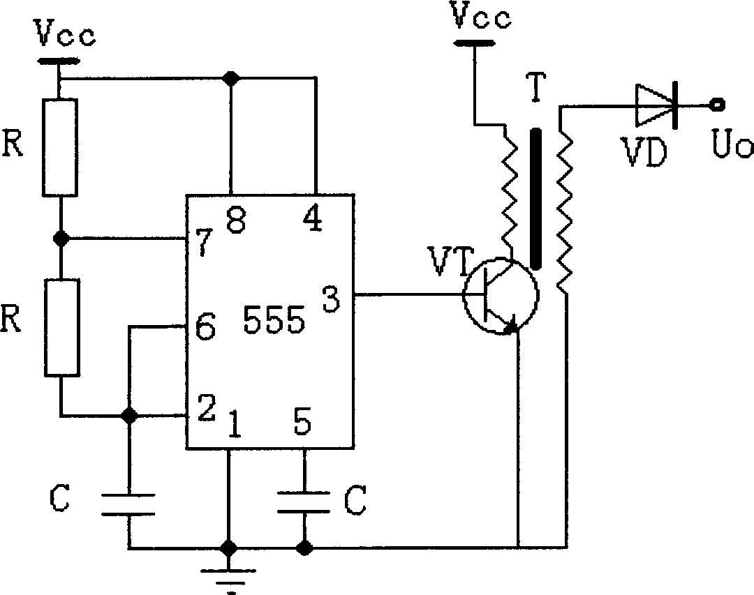
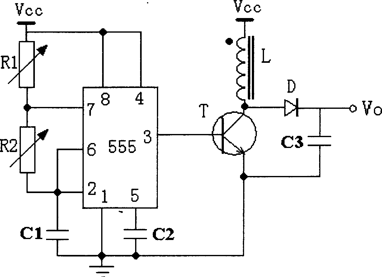
[0020] see figure 2 , figure 2 It is a schematic circuit diagram of a specific embodiment of the inductance step-up DC converter of the present invention. It can be seen from the figure that the small inductance step-up DC converter of the present invention adopts the 555 integrated timer as the square wave generator, and the first resistor R1 and the second resistor R2 are respectively connected between the 6th pin and the 7th pin of the 555 and Between pin 7 and power supply Vcc, the node between pin 6 and pin 2 of the 555 integrated timer and the second resistor R2 is grounded through the first capacitor C1, pin 1 is grounded, and pin 5 is grounded through the second capacitor C2 , the 4th and 8th pins are connected to the power supply Vcc, the 3rd pin is connected to the control pole of the switching transistor T, the collector of the switching transistor T is connected to the power supply Vcc through a booster, and the emitter of the switching transistor T is grounded,...


PUM


Abstract

This invention relates to a small sized inductance booster DC converter. Multiple vibrators generate square-wave signals with adjustable frequency and duty-ratio to drive the conduction and end of a switch triode, the inductor current serial to the triode collector loop varies along with the conduction and end of the triode, an instant high voltage is generated at one end of the inductor when it is connected to the end jump, stable high voltage and small current output are got by rectification and filter according to self inductance effect.

Description

technical field [0001] The invention relates to a DC converter, in particular to a small inductance step-up DC converter with high voltage and low current output, which is suitable for photoelectric conversion devices, sensor bias circuits and avalanche photodiode detectors in small portable products. Background technique [0002] With the development of microelectronics technology, electronic equipment is improving towards integration, portability and digitalization, which requires the modules in the system to be more and more miniaturized and low power consumption. Therefore, in addition to stability, reliability, and high efficiency, miniaturization and light weight are also very urgent needs among the technical requirements put forward by the electronic system for the power supply device. [0003] At present, many electronic systems are directly powered by batteries or only by a basic voltage, but many detectors, sensors and modules require a bias voltage much higher tha...

Claims


Application Information

Patent Timeline
Patent Type & Authority Applications(China)
IPC IPC(8): H02M3/335
Inventor 鲍星合陈刚
Owner SHANGHAI INST OF OPTICS & FINE MECHANICS CHINESE ACAD OF SCI
Why Eureka
Try Eureka