

High-pressure discharge lamp operation device and illumination appliance having the same
A technology for high-pressure discharge lamps and lighting devices, which is applied in the use of gas discharge lamps, high-efficiency power electronic conversion, and components of lighting devices, etc., can solve the problems that the size of electronic circuit modules cannot be easily reduced, and achieve reduction The effect of size and cost
- Summary
- Abstract
- Description
- Claims
- Application Information
AI Technical Summary
Problems solved by technology
Method used
Image


Examples
no. 1 example
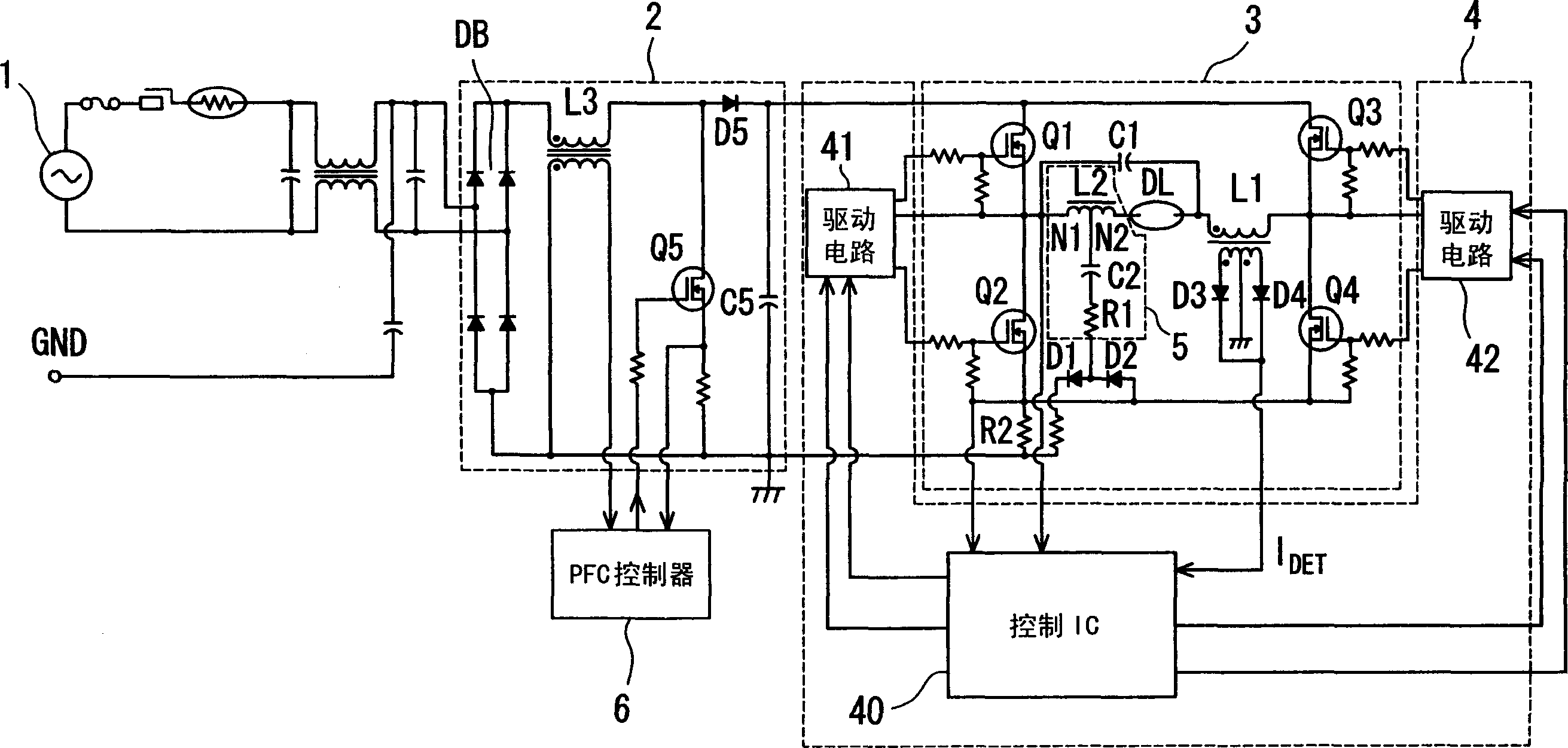
[0108] figure 1 is a circuit diagram of the first embodiment of the high pressure discharge lamp lighting device according to the present invention. The high pressure discharge lamp lighting device according to this embodiment includes an AC power source 1 , a rectification circuit 2 , a lighting circuit 3 , a control circuit 4 , a resonant circuit 5 , and a power factor correction (PFC) controller 6 .
[0109] The rectification circuit 2 has a bridge rectifier DB connected to the AC power source 1 through a noise filter circuit and a line protection device. The bridge rectifier DB performs full-wave rectification of the AC voltage supplied from the AC power supply 1, and converts the AC voltage into a DC voltage. One terminal of the inductor L3 is connected to the high potential side of the output terminal of the bridge rectifier DB. A switching element Q5 such as a MOSFET (Metal Oxide Silicon Field Effect Transistor) is connected between the low potential side of the outp...
no. 2 example
[0135] Figure 6 is a circuit diagram of a second embodiment of the high pressure discharge lamp lighting device according to the present invention. The high pressure discharge lamp lighting device according to the present embodiment differs from the first embodiment in the configuration of the lighting circuit. More specifically, in the second embodiment, the switching elements Q3 and Q4 of the lighting circuit 3 in the first embodiment are replaced with capacitors C3 and C4, and the drive circuit 42 and the current detection resistor of the control circuit 4 are eliminated. R2.
[0136]In the lighting circuit 7 according to the present embodiment, a half-bridge circuit is constituted by the switching elements Q1 and Q2 and the capacitors C3 and C4 to convert the DC power supplied from the rectifier circuit 2 into AC power and supply the AC power to to the lamp DL. One terminal of each of the switching element Q1 and the capacitor C3 is connected to the high potential side...
no. 3 example
[0150] Figure 9 is a circuit diagram of a third embodiment of the high pressure discharge lamp lighting device according to the present invention. The circuit configuration of this embodiment is basically the same as that of the first embodiment. The point of difference is that the voltage at the connection point between the inductor L1 and the lamp DL is input to the control IC of the control circuit 4 so that the voltage can be detected.
[0151] The following reference Figures 10A to 10E and Figure 11 The operation of this embodiment will be described.
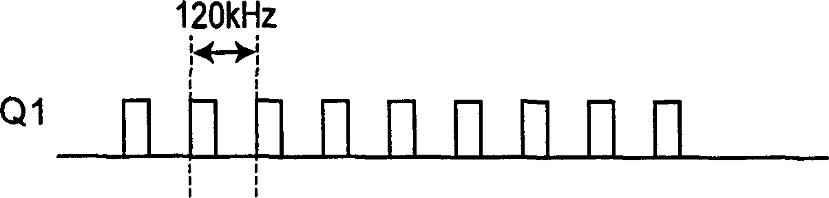
[0152] Figures 10A to 10D Drive signals Q1 and Q4 output from drive circuits 41 and 42 to switching elements Q1 and Q4 are shown when switching element pair Q1 and Q4 are alternately turned on / off at switching frequency fsw1 having a duty factor of 40%. Figure 10B and 10C Shown are drive signals Q2 and Q3 output from drive circuits 41 and 42 to switching elements Q2 and Q3 when switching element pair Q2 and Q3 ar...
PUM
| Property | Measurement | Unit |
|---|---|---|
| Resonant frequency | aaaaa | aaaaa |
Abstract
Description
Claims
Application Information