Method and device for measuring time interval through delay line in cascaded two stages

A time interval and time measurement technology, applied in the field of optical disc readout signal analysis and detection, can solve the problems of high cost, complex design process, long design and processing cycle, etc.

Inactive Publication Date: 2005-11-16
TSINGHUA UNIV
View PDF0 Cites 36 Cited by
  • Summary
  • Abstract
  • Description
  • Claims
  • Application Information

AI Technical Summary

Problems solved by technology

But this method is based on digital CMOS technology and ASIC chip design, the cost of one design is very high, especially when

Method used


Image

  • Method and device for measuring time interval through delay line in cascaded two stages
  • Method and device for measuring time interval through delay line in cascaded two stages
  • Method and device for measuring time interval through delay line in cascaded two stages

Examples


Embodiment Construction

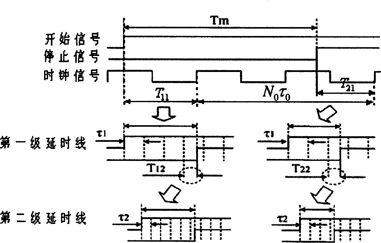
[0051] Figure 5 The device circuit shown as the two-stage cascaded delay line method is realized in an XC2V80-6-fg256 chip, which is a Virtex II series FPGA chip of Xilinx Company. The basic clock operating frequency of the system is 200MHz, and it is used as the counting clock signal of the 18-bit binary counter. Resolution τ of the first stage delay line 1 About 800 picoseconds. Since the logic unit delay or path delay that can be obtained in the FPGA chip is basically hundreds of picoseconds, if you want to obtain a resolution below 100ps, the second-level delay line can no longer be designed according to the first-level delay line method . The design method adopted in the present invention makes the resolution τ of the second stage delay line 2 The resolution is 75ps, which breaks through the limitation of circuit physical delay and obtains higher resolution. In order to ensure that the measurements do not interfere with each other and measure continuously, before ea...


PUM


Abstract

A method for measuring time interval with two stage cascade delay line includes measuring numbers of clock leading edge in time interval to be measured i e cycle number of clock, measuring two time intervals not being complete cycle of front and back time intervals to be measured, sending those less than resolution of first stage relay line to the second stage for further subdivision, calculating out value of time interval to be measured by utilizing measured results. The measuring device is composed of only delay unit and D trigger for both delay lines.

Description

technical field [0001] The invention relates to high-precision time interval measurement technology, and belongs to the field of optical disc read signal analysis and detection Background technique [0002] The most common method of measuring time intervals is the pulse counting method, the principle of which is as follows figure 1 shown. The high / low level (that is, the time interval) of the signal to be tested controls the switch of the high-frequency counter, and the time width to be tested can be obtained by calculating the number of pulses during the period. Assuming that the number of pulses measured is n, the counting clock cycle T 0 , then the actual measurement result T w 'is an integer multiple nT of the counting clock period 0 . The measurement process of this method is relatively simple, but the measurement accuracy and resolution are not easy to improve. Since the position of the rising edge or falling edge of the signal to be measured relative to the coun...

Claims


Application Information

Patent Timeline
IPC IPC(8): G04F10/00H03K5/14
Inventor 徐端颐袁海波沈全洪
Owner TSINGHUA UNIV
Why Eureka
Try Eureka