D trigger with resetting and/or setting functions, and based on conditional preliminary filling structure

A trigger and function technology, which is applied in the direction of electrical components, pulse generation, and electrical pulse generation, etc., can solve the problem of extremely asymmetrical rising edge delay and falling edge delay at the output end of the trigger circuit, and lack of second-level reset position. Design, structural circuit complexity and other issues

Inactive Publication Date: 2005-11-16
TSINGHUA UNIV
View PDF0 Cites 31 Cited by
  • Summary
  • Abstract
  • Description
  • Claims
  • Application Information

AI Technical Summary

Problems solved by technology

However, the problem with the SAFF_CP circuit is that since the output latch circuit adopts a cross-coupled NAND2 (NAND2: two-input NAND gate) structure, the delay of the rising edge and falling edge of the output of the flip-flop circuit will be extremely different. Symmetry, which poses potential problems for the use of circuit cells
This kind of structural circuit is relatively complicated, and only the first-level reset method is given, without considering the priority design when the reset bits appear at the same time, lack of design for different second-level reset bits, and cannot be simply applied image 3 The SAFF_CP flip-flop structure shown

Method used


Image

  • D trigger with resetting and/or setting functions, and based on conditional preliminary filling structure
  • D trigger with resetting and/or setting functions, and based on conditional preliminary filling structure
  • D trigger with resetting and/or setting functions, and based on conditional preliminary filling structure

Examples


Embodiment Construction

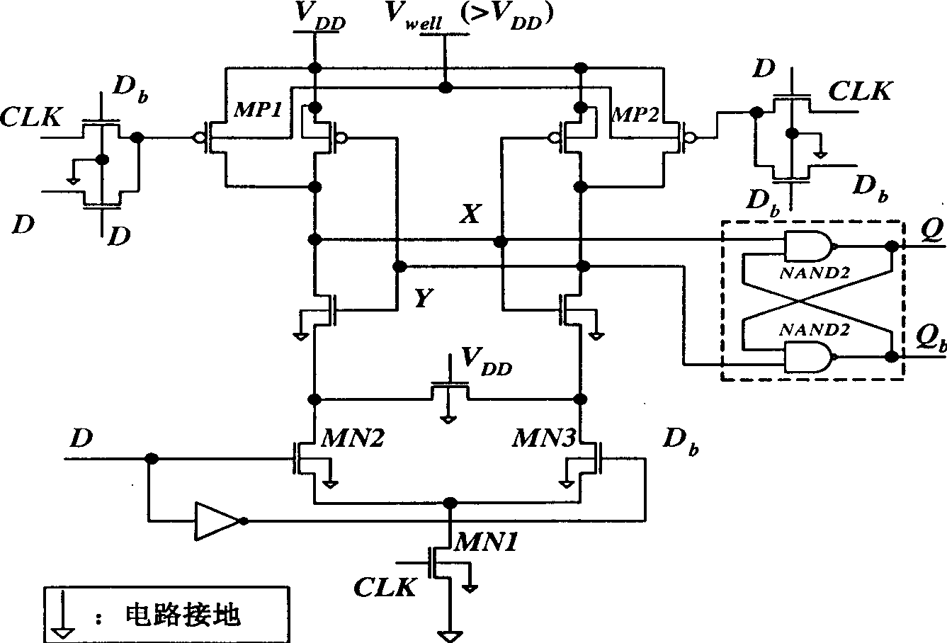
[0108] The technical solution for the present invention to solve its technical problems is: the present invention proposes a flip-flop FFDSRHD1X_SCB_FCS with a reset position end based on a conditional prefill structure, such as Figure 6 Show. Figure 5 shows that the circuit is Figure 6 prototype. FFDSRHD1X_SCB_FCS flip-flop has the characteristics of using conditional precharge technology to reduce the power consumption of the flip-flop circuit itself, and has the function of setting and resetting. Figure 5 The basic structure is a conditional pre-charge flip-flop, and its working principle is as follows: first, four MOS tubes are used to preprocess the CLK signal and D signal, mainly CLK "or (OR)" D, CLK "or (OR)" Db , and then add these two signals to the gates of the two pull-up drive transistors, and precharge the first-stage latch through them; the center of the first-stage latch is composed of MP2, MP3, MN5, and MN6 to form a sense amplifier structure. This stru...


PUM


Abstract

Characters of the invention are as following: besides structure of sensitive amplifier is adopted in latch in first stage, pull-up and pull-down are carried out for two complemental output ends by using two pieces of P tubes and two pieces of N tubes at power source end and complemental output ends respectively. Control signals pulled-up and pulled-down are set and reset signals. Two pieces of phase latches in single clock with identical circuit parameter are adopted in latch in second stage. Potential retention unit structured from two inverters connected at headers is added between output ends of two pieces of phase latches. Comparing prior art, the invention saves energy 20% under same testing condition. Moreover, the invention possesses features of simple structure, small area of circuit, good characteristics of circuit time delay, setup time and metastable state time.

Description

technical field [0001] The technical field of the direct application of the D flip-flop based on the conditional precharge structure with the reset setting function is the low power consumption flip-flop circuit design with the reset setting function based on the conditional precharge structure. The proposed circuit is a kind of low-power CMOS flip-flop circuit unit which is suitable for low-swing clock signal network technology and needs to reset the set terminal. Background technique [0002] With the advancement of CMOS integrated circuit manufacturing technology, the scale and complexity of integrated circuits are increasing day by day, and the power consumption and heat dissipation of integrated circuits have been paid more and more attention from industry and academia. Based on the current integrated circuit design style, in large-scale digital circuit systems, the energy consumed by the clock network accounts for a high proportion of the total energy consumption of th...

Claims


Application Information

Patent Timeline
Patent Type & Authority Applications(China)
IPC IPC(8): H03K3/012
Inventor 杨华中魏鼎力乔飞汪蕙
Owner TSINGHUA UNIV
Why Eureka
Try Eureka