Supercharge Your Innovation With Domain-Expert AI Agents!

Liquid cooling system

A technology of liquid cooling and cooling system, which is applied in the direction of cooling fluid circulation device, cooling/ventilation/heating transformation, cooling/ventilation of substation/switchgear, etc., and can solve problems such as cooling concept without detailed description of heat removal

Inactive Publication Date: 2005-11-16
RITTALWERK RUDOLF LOH GMBH & CO KG
View PDF2 Cites 12 Cited by
  • Summary
  • Abstract
  • Description
  • Claims
  • Application Information

AI Technical Summary

Problems solved by technology

The cooling concept for removing heat in the area of ​​individual components is not described in detail in this document

Method used


Image

  • Liquid cooling system

Examples


Embodiment Construction

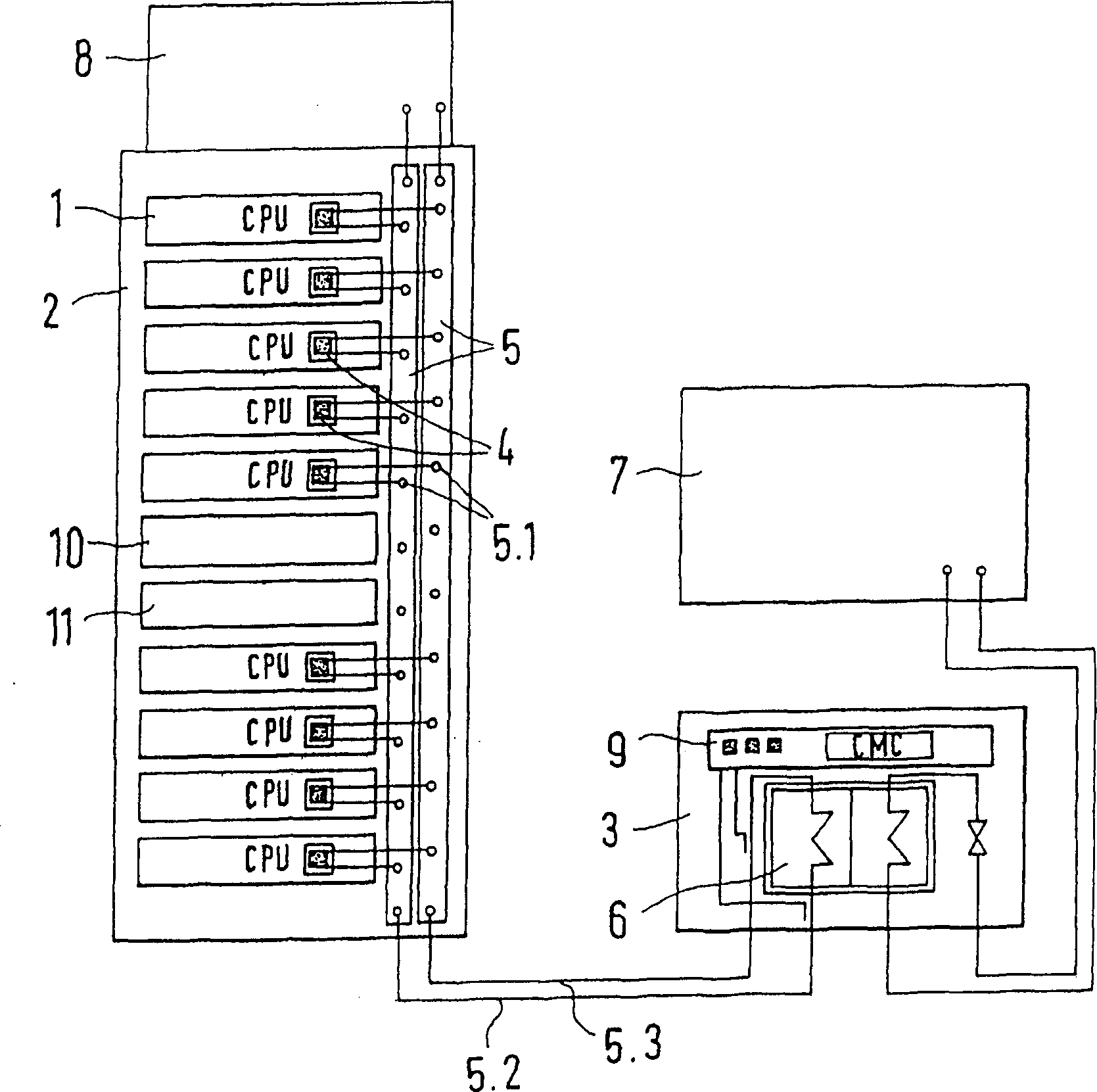
[0015] figure 1 A schematic diagram showing a configuration example of a liquid cooling system for cooling a plurality of electronic components 1 arranged in a rack 2, wherein each electronic component as a main heat generating source has at least one housing containing the electronic component 1 Central processing unit (CPU) 1.1 with high computing power.

[0016] In order to cool the electronic component 1, in particular the processor unit or computing unit 1.1, which is constructed as an integrated assembly, a cooling unit 4 with ducts is mounted on the assembly body with tight heat-conducting contact, through which cooling liquid is guided as far as possible long path. The liquid cooling unit with the cooling unit 4 is connected via the respective forward and return branch lines via corresponding branch structures 5.1 to coupling elements in the vertical section of the central liquid line system 5 running in the frame. The central liquid line system 5 also has a forward ...


PUM


Abstract

The invention relates to a liquid cooling system comprising several cooling units (4) which are arranged in a rack (2) or switch cabinet and which are individually associated with electronic modules (1) which are to be cooled. Said system also comprises a monitoring and control device (9) for monitoring the cooling temperature. Effective cooling and monitoring of temperature is maintained by virtue of the fact that the cooling units (4) are configured as liquid cooling units and are connected by means of branches (5.1) to a common central liquid line system (5) which is integrated into the rack (2) or switch cabinet and that the control and monitoring device for monitoring the cooling temperature is embodied in the central liquid line system (5) and produces an error signal when a predefined or predefinable threshold temperature has been exceeded in a liquid return branch (5.3) or a predefined or predefinable threshold temperature difference between a temperature in a forward branch (5.2) and a temperature in the return branch (5.3) has been exceeded or when the flow of fluid falls below a predefined or predefinable threshold value.

Description

technical field [0001] The invention relates to a liquid cooling system with a plurality of cooling units installed in racks or switchgear cabinets and provided separately for cooling electronic components, and with a monitoring and control device for monitoring the cooling temperature. Background technique [0002] Such a liquid cooling system is described in DE 19609651 C2 in connection with a switchgear air conditioning unit. In this case, the liquid cooling system is formed, for example, as a cooling device or cooling unit with a gas / water heat exchanger and represents a component of the overall air conditioning system, which is controlled by means of a superordinate monitoring and control device. Monitoring and control and regulation. Using the cooling device in combination with the monitoring and control device, various control concepts of the air conditioner can be implemented according to different application situations and user wishes. In this case, individual el...

Claims


Application Information

Patent Timeline
Patent Type & Authority Applications(China)
IPC IPC(8): F25D17/02H05K7/20
CPCH05K7/2079F25D17/02H05K7/20781
Inventor 迈克尔·尼古莱马丁·多里赫海因里希·斯特拉克宾马库斯·海恩乔尔格·克雷林
Owner RITTALWERK RUDOLF LOH GMBH & CO KG
Features
  • R&D
  • Intellectual Property
  • Life Sciences
  • Materials
  • Tech Scout
  • Unparalleled Data Quality
  • Higher Quality Content
  • 60% Fewer Hallucinations
Learn More