Ultrashort pulse time and space purifying device

An ultra-short pulse, purification device technology, applied in laser parts, instruments, electrical components, etc., can solve the problems of increased cost, reduced efficiency, complex system, etc., to achieve simple device, compressed pulse width, and maintain pulse time purification. Effect

An ultra-short pulse, purification device technology, applied in laser parts, instruments, electrical components, etc., can solve the problems of increased cost, reduced efficiency, complex system, etc., to achieve simple device, compressed pulse width, and maintain pulse time purification. Effect

CN1700536AInactive Publication Date: 2005-11-23SHANGHAI INST OF OPTICS & FINE MECHANICS CHINESE ACAD OF SCI

Image

  • Ultrashort pulse time and space purifying device
  • Ultrashort pulse time and space purifying device
  • Ultrashort pulse time and space purifying device

Examples


Embodiment Construction

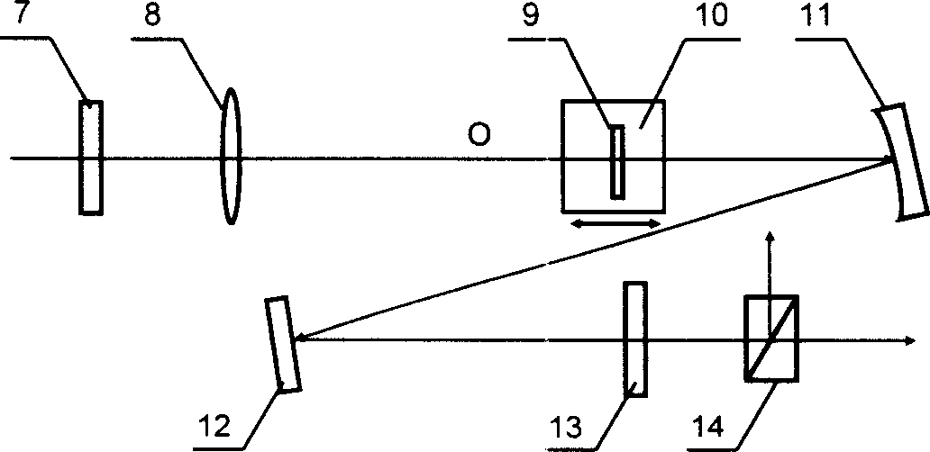
[0026] Below by embodiment the present invention will be further described, but should not limit protection scope of the present invention with this. see first figure 2 , figure 2 It is a structural schematic diagram of a specific embodiment of the ultrashort pulse time and space purification device of the present invention. As can be seen from the figure, the structure of the ultrashort pulse time and space purification device of the present invention: on the optical path of the input linearly polarized ultrashort pulse laser, there are: the first 1 / 4 wave plate 7, the focusing lens 8, the second 1 / 4 Wave plate 13 and analyzer 14, the optical axis direction of this analyzer 14 is perpendicular to the polarization direction of the described incident linearly polarized ultrashort pulse laser, and the fast axis direction of the first 1 / 4 wave plate 7 is perpendicular to The polarization direction of the incident linearly polarized ultrashort pulse laser is 22.5Β°, which is ch...


PUM


Abstract

This invention relates to super short impulse time and space purifying device, which comprises one quarter wave sheet, focus lens, second quarter wave sheet and bias tester and is characterized by the following: a, the said first and second quarter wave sheets are as zero quarter wave sheet with rapid axis direction crossed; b, there are located with non-linear positive transparent solid material and silver concaved reflection lens between the said focus lens and second quarter wave sheet; c, the said silver coated concaved reflection lens and the said focus lens are at same height with distance of two focus as co-focus point.

Description

technical field [0001] The invention relates to an ultrashort pulse laser, in particular to an ultrashort pulse time and space purification device, which can simultaneously improve the time contrast and space mode of an ultrashort pulse without using additional dispersion compensation components, and the device is simple and easy to build, and is mainly applicable to In femtosecond ultrashort laser pulses, it is applied in the field of high-intensity ultrafast laser technology and ultrafast strong field physics research. Background technique [0002] In the past few decades, the production and application of femtosecond lasers have made great progress. With the emergence of titanium-doped sapphire (Ti: sapphire) mode-locked lasers and chirped pulse amplification (CPA) technology, desktop equipment It is possible to obtain ultra-intense and ultra-short laser pulses. Ultra-intensive and ultra-short laser pulses are important tools in many basic researches, and play an irrepla...

Claims


Application Information

Patent Timeline
23 Nov 2005
Publication
CN1700536A
IPC
H01S3/00
Inventors
ι™ˆζ™“δΌŸ; 冷雨欣