
Method for producing scattering ray raster or collimator with ray absorption material

A collimator, ray technology, applied in the direction of using diaphragm/collimator, instrument for radiological diagnosis, radiation measurement, etc., can solve the problems of laborious and expensive manufacturing methods, and confusion of collimators.

Inactive Publication Date: 2005-12-14
SIEMENS AG
View PDF6 Cites 11 Cited by
  • Summary
  • Abstract
  • Description
  • Claims
  • Application Information

AI Technical Summary

Problems solved by technology

This is a relatively inexpensive solution, but it has the disadvantage that, especially when using solid-state cameras with detection components arranged in a matrix, for example in cadmium-zinc-tellurium compound detectors, due to the collimator Rougher structures can have disturbing aliasing effects
Thus, these fabrication methods are also laborious and expensive

Method used


Image

  • Method for producing scattering ray raster or collimator with ray absorption material
  • Method for producing scattering ray raster or collimator with ray absorption material
  • Method for producing scattering ray raster or collimator with ray absorption material

Examples


Embodiment Construction

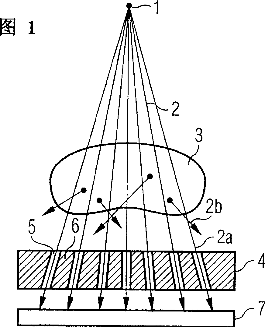
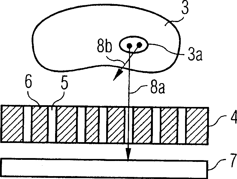
[0031] A typical situation during the radiographing of an object 3 is schematically depicted in FIG. 1 . The object 3 is located between an x-ray tube focus 1 which can be regarded as a point x-ray source and a detection surface 7 . The x-ray beam 2 emitted by the focal point 1 of the x-ray source spreads linearly in the direction of the x-ray detector 7 and passes through the object 3 there. The primary ray 2a emitted by the X-ray focal point 1 passing through the object 3 and impinging on the detection surface 7 produces a spatially resolvable attenuation value distribution on the detection surface 7 due to the object 3 . A part of the x-rays 2 emitted by the x-ray focus 1 is scattered in the object 3 . The resulting scattered radiation 2 b has a negative effect on the desired image information and significantly deteriorates the signal-to-noise ratio when impinging on the detector 7 . To improve the image quality, a scattered radiation grid is then arranged upstream of the...


PUM


Abstract

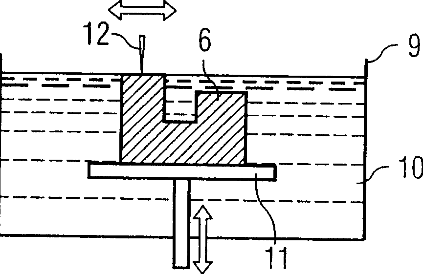
The invention relates to a method for producing a scattered radiation grating or collimator (4) for a radiation type, the scattered radiation grating or collimator consisting of at least one geometrically predeterminable base body (6) The base body (6) has a channel or a channel groove (5) extending between its two opposing surfaces for the passage of the primary beam of the beam type. The method is characterized in that the base body ( 6 ) is formed by die-casting or stereolithography from a structural material that absorbs strongly this type of radiation. The use of the method allows the production of scattered radiation gratings or collimators with high precision using only a small number of method steps.

Description

technical field [0001] The invention relates to a method for producing a scattered radiation grating or collimator for a type of radiation, the scattered radiation grating or collimator consisting of at least one geometrically predeterminable base body with A channel or channel slot extending between its two opposing surfaces for the passage of the primary ray of that ray type. Background technique [0002] Today, high demands are placed on the image quality of radiographs in x-ray imaging technology. In such imaging, as is done especially in medical X-ray diagnostics, an object to be examined is penetrated by X-rays of an approximately point-like X-ray source, and at the point opposite the X-ray source One side obtains the attenuation distribution of the X-rays two-dimensionally. For example, the x-rays attenuated by the object can also be detected line by line in a computed tomography system. In addition to x-ray film and gas detectors, solid-state detectors can also be...

Claims


Application Information

Patent Timeline
Patent Type & Authority Applications(China)
IPC IPC(8): G21K1/02A61B6/06G01T7/00
CPCA61B6/4258G21K1/025
Inventor 安德烈亚斯·弗罗因德比约恩·海斯曼哈拉尔德·马克尔马丁·谢弗托马斯·冯德哈尔
Owner SIEMENS AG
Learn More