Thermal tube and producing method thereof

A manufacturing method and technology of heat pipes, which are applied in indirect heat exchangers, heat exchange equipment, lighting and heating equipment, etc., can solve the problems of increasing liquid return resistance, reducing the amount of working liquid, increasing capillary force, etc., to improve heat transfer. performance, improved reliability, and faster reflow

Inactive Publication Date: 2005-12-14
HONG FU JIN PRECISION IND (SHENZHEN) CO LTD +1
View PDF0 Cites 22 Cited by
  • Summary
  • Abstract
  • Description
  • Claims
  • Application Information

AI Technical Summary

Problems solved by technology

However, with the rapid increase of the calorific value of electronic components, this heat pipe structure also shows its shortcomings. The capillary structure in the heat pipe plays the role of backflow of the working liquid, so the condensed working liquid needs to be sucked into the capillary structure, and the capillary structure is commonly used Such as grooves, etc. cannot quickly suck the condensed working liquid into the capillary structure: if the capillary radius of the capillary structure is reduced, the capillary force will be increased to increase the amount of working liquid it sucks, but at the same time it will increase the absorption of the liquid. If the capillary radius of the capillary structure is increased, its resistance to liquid reflux will be reduced, but at the same time, its capillary force will be reduced to reduce the amount of working liquid sucked, which also leads to the loss of working liquid. Insufficient reflux, moreover, the currently commonly used heat pipe processing methods cause defects in the capillary structure, such as the capillary structure made by the powder sintering method is relatively brittle, the intercalated wire mesh structure is not in close contact with the heat pipe wall, and the grooved capillary structure is affected. The shape and density of the machined grooves are limited due to the limitation of the tool
In addition, the heat pipe needs to be kept under a certain vacuum condition before it can be used normally, and various materials have a certain permeability to gas, so the vacuum degree in the heat pipe will be reduced, so that the heat pipe cannot work normally and the reliability of the heat pipe will be reduced.

Method used


Image

  • Thermal tube and producing method thereof
  • Thermal tube and producing method thereof

Examples


Embodiment Construction

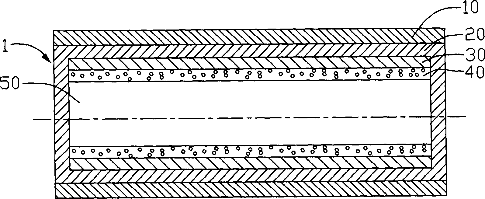
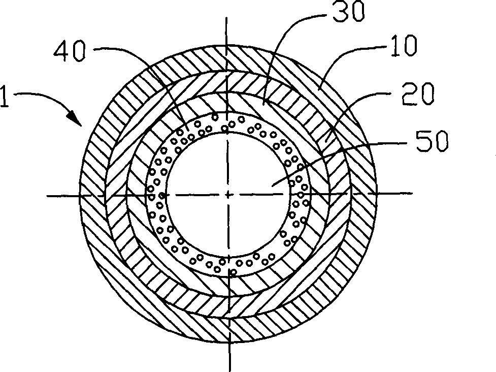
[0013] Please refer to Figure 1 to Figure 2 As shown in the heat pipe of the present invention, the shell of the heat pipe 1 has four layers, from the outside to the inside of the heat pipe 1, there are protective layer 10, shell layer 20, capillary structure layer 30 and hydrophilic layer 40, and the cavity of the heat pipe 1 50 contains an appropriate amount of working medium, the working medium is selected from liquids with low boiling point and stable chemical properties such as ethanol, pure water, etc., and nano powders such as carbon nanotubes, nano carbon spheres, nano copper powder particles or their The mixture to increase the heat transfer of the working medium. Wherein, the protective layer 10 is made of nano-materials, such as carbon nanotubes, nano-copper, nano-aluminum, and nano-copper-aluminum alloys. The above-mentioned nano-materials can be deposited on the shell layer 20 to form a layer by vacuum coating technology. A film layer with a thickness between 10...


PUM

PropertyMeasurementUnit
thicknessaaaaaaaaaa
thicknessaaaaaaaaaa
thicknessaaaaaaaaaa

Abstract

The heat pipe includes one casing, at least one capillary structure layer adhered to the inner wall of the casing and work medium filled into the heat pipe, where, the casing has at least one protecting layer and the capillary structure layer is provided with one hydrophilic layer. The making process of the heat pipe includes the steps of: 1. providing one metal plate; 2. surface treatment via a laser technological process; 3. vacuum filming to deposit the capillary structure layer and the hydrophilic layer on side of the metal plate at vacuum degree higher than 5E(-6) Pa and deposit protecting layer on the other side of the metal plate; 4. winding the metal plate into pipe and sealing the seam and one end to form heat pipe casing; 5. filling the casing with work medium and pumping to form vacuum; and 6. sealing the casing.

Description

【Technical field】 [0001] The invention relates to a heat pipe and a manufacturing method thereof, in particular to a heat pipe with good heat dissipation effect and high reliability applied to heat dissipation of electronic components. 【Background technique】 [0002] Electronic components such as the central processing unit will generate a lot of heat during normal operation. If the heat generated is not removed in time, the heat will accumulate and cause the temperature to rise, which will seriously affect the normal operation of electronic components. The problem of heat dissipation has become a problem. Problems that need to be solved urgently to affect the product to move towards higher performance. [0003] Commonly used heat sinks are made of metal materials such as aluminum or aluminum alloy. Due to their limited thermal conductivity, it is difficult to fully transfer the heat generated by electronic components to the heat dissipation fins and dissipate it quickly, so...

Claims


Application Information

Patent Timeline
Patent Type & Authority Applications(China)
IPC IPC(8): F28D15/00F28D15/04H01L23/427
CPCF28F19/02F28D15/046B82Y10/00F28F2245/02
Inventor 陈杰良
Owner HONG FU JIN PRECISION IND (SHENZHEN) CO LTD
Why Eureka
Try Eureka