High-pressure gas atomizing nozzle
A high-pressure gas atomization and nozzle technology, applied in the direction of liquid injection devices, injection devices, etc., can solve the problems of atomization termination, nozzle clogging, coarse powder particle size, etc., achieve particle size refinement, ensure continuity, and increase powder output ratio Effect
- Summary
- Abstract
- Description
- Claims
- Application Information
AI Technical Summary
Problems solved by technology
Method used
Image
Examples
Embodiment 1
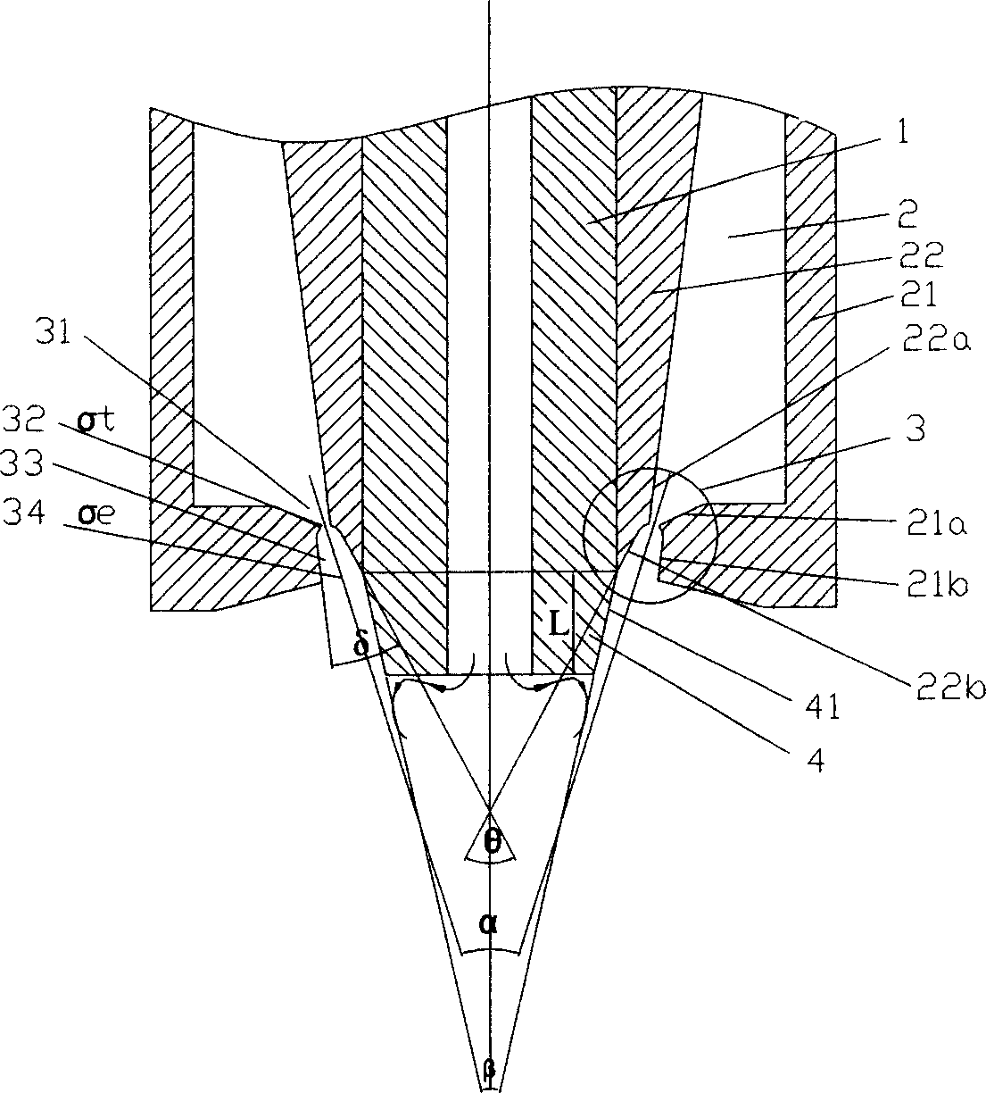
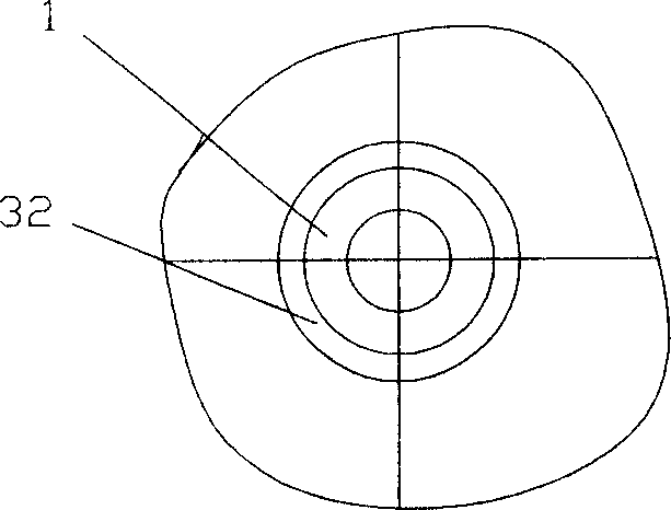
[0020] A Laval nozzle throat is such as figure 2 The high-pressure gas atomizing nozzle with the annular gap structure shown, its cross-sectional view is as follows figure 1 As shown, it includes a guide tube 1, the guide tube 1 is provided with an air cavity 2 surrounding it, the wall surfaces 21a, 21b of the outer cavity wall 21 of the air cavity 2 and the wall surfaces 22a, 22b of the inner cavity wall 22 A Laval nozzle structure 3 is formed near the top of the draft tube 1. The Laval nozzle structure 3 includes a converging portion 31, a throat 32, and a divergent portion 33. The outside of the tube wall near the top of the draft tube 1 is conical 4, and its conical surface The extension line of 41 forms an included angle β, and the extension line of the inner cavity wall surface 22b of the air chamber 2 in the divergent part 33 of the Laval nozzle structure 3 forms an included angle θ, and the angle θ is greater than or equal to the angle β, and the divergent part 33 of ...
Embodiment 2
[0028] A kind of Laval nozzle throat 32 is such as figure 2 For the high-pressure gas atomizing nozzle with circular seam structure shown, the angle β=30°, the angle α=40°, the angle δ=10°, L=2mm, and the cross-sectional area of the annular seam is 16mm 2 , The ratio of бe to бt is 5:1, and the central aperture of the guide tube 1 is 4.2mm. The basic composition of the material is Fe70Ni30. Add 21Kg of pure iron rod and 9Kg of pure nickel plate into the MgO crucible of the atomization furnace. The atomization system is evacuated, and the intermediate frequency power supply is 90KW for 45min. When the furnace temperature rises to 1600°C, pour the liquid into the tundish for atomization. The atomization adopts the atomization pressure of 3.8Mpa, and the gas is high-purity nitrogen. The particle size distribution of atomized powder is as follows: Figure 6 As shown, 9.2wt% of the atomized powder is less than 10 μm, 31.2wt% is less than 20 μm, and 76.3wt% is less than 40 μm....
Embodiment 3
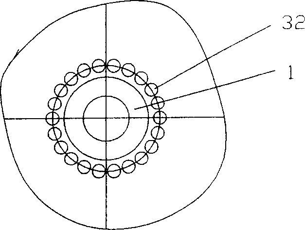
[0030] In this embodiment, the nozzle with the throat 32 of the nozzle as an annular hole structure is adopted, which is composed of 20 individual annular holes. Angle β=40°, angle α=30°, angle δ=24°, L=5mm, the ratio of бe to бt is 5:1, and the total cross-sectional area of the ring hole is 20mm 2 , The central aperture of the guide tube 1 is 4.5mm. The basic composition of the material is FeSi9.6Al5.4. Put 21.3Kg of pure iron and 2.4Kg of industrial pure silicon into the crucible of the atomization furnace. The atomization system is vacuumed, and the intermediate frequency power supply is 70KW. After 40 minutes, the charge is melted, and 1.35Kg of aluminum is added in a protective atmosphere. Rise to 1550°C to prepare for atomization, the atomization pressure is 4.5MPa, and the gas is high-purity nitrogen. The particle size distribution of atomized powder is as follows: Figure 8 As shown, the average particle size of the atomized powder is 18.8 μm, 31.6 wt% is less tha...
PUM
 Abstract
Description
Claims
Application Information
 - R&D
- Intellectual Property
- Life Sciences
- Materials
- Tech Scout
- Unparalleled Data Quality
- Higher Quality Content
- 60% Fewer Hallucinations
Browse by: Latest US Patents, China's latest patents, Technical Efficacy Thesaurus, Application Domain, Technology Topic, Popular Technical Reports.
© 2025 PatSnap. All rights reserved.Legal|Privacy policy|Modern Slavery Act Transparency Statement|Sitemap|About US| Contact US: help@patsnap.com


